
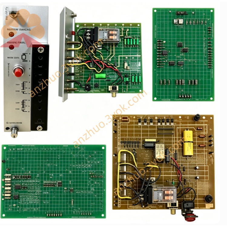
0-57C404-1E
Description
Model Definition
0-57C404-1E: Full part number
Leading 0: Factory‑original, unmodified
57C404: Base model (4‑channel analog input)
‑1: 16‑bit high resolution
E: Extended temperature (‑20°C to +70°C) + conformal coating
57C404: Core model (standard 12‑bit analog input)
Series: AutoMax 57C Series (Reliance PLC I/O) / DCS 5000 Series
Technical Specifications
General
Brand: RELIANCE (Reliance Electric / Baldor Reliance)
Type: 4‑Channel High‑Speed Analog Input Module
Form Factor: 1‑slot AutoMax rack‑mount
Dimensions: 11.75 in (H) × 3.5 in (W) × 1.2 in (D) approx
Weight: ~1.0 kg (2.2 lbs)
Operating Temperature: ‑20°C to +70°C (‑1E extended range)
Storage Temperature: ‑40°C to +85°C
Humidity: 5%–95% non‑condensing
Isolation: 1500 Vrms channel‑to‑backplane, channel‑to‑channel isolation
Certifications: CE, RoHS, UL listed
Resolution: 16‑bit (‑1E); standard 57C404 = 12‑bit
Analog Input Ratings
Total Channels: 4 (isolated, differential)
Signal Type: Voltage or Current (selectable per channel)
Voltage Ranges: ±10 VDC, ±5 VDC, 0–10 VDC, 0–5 VDC
Current Ranges: 4–20 mA, 0–20 mA (external 250Ω shunt)
Sampling Rate: 100 kHz total (25 kHz per channel max)
Accuracy: ±0.02% FS (25°C); ±0.05% FS (‑20°C to +70°C)
Input Impedance: >1 MΩ (voltage); 250Ω (current)
Protection: Overvoltage, overcurrent, ESD, transient suppression
Electrical
Backplane Power: 5 VDC ±5% (from AutoMax rack)
Current Draw: 0.9 A (typical), 1.3 A (max)
Fuse: 1 A onboard fuse (per channel bank)
Interface & Communication Configuration
Physical Interfaces
Front Panel: 4 channel terminals (CH1–CH4) + common; LED per channel (green = active, red = fault)
Backplane: AutoMax proprietary edge connector (power + Multibus communication)
LED Indicators:
PWR: Backplane power (green = OK)
RUN: Module active (steady = run, flash = init)
FLT: Fault (red = overrange/short)
CH1–CH4: Channel status (green = sampling, red = fault)
Communication
Bus Protocol: AutoMax Multibus (parallel, high‑speed)
Data Rate: 2 Mbps (backplane)
Compatibility: AutoMax 57C series racks (57C331/332/334 chassis)
Data Format: 16‑bit signed/unsigned analog values, parity‑checked
Core Functions
4‑Channel Isolated Analog Input: Precision acquisition of voltage/current signals.
16‑Bit High Resolution (‑1E): Superior accuracy for critical process/motion parameters.
High‑Speed Sampling: Up to 100 kHz total for dynamic signal monitoring.
Multi‑Range Support: Software‑selectable voltage/current ranges per channel.
1500 Vrms Isolation: Protects PLC from field‑side noise, spikes, and ground loops.
Conformal Coating + Extended Temp (‑1E): Reliable in humid, dusty, cold/hot environments.
Fault Detection: Overrange, short‑circuit, and open‑loop detection with FLT alarm.
Application Scenarios
Legacy AutoMax Retrofits: Direct replacement for 57C404 / 0‑57C404‑1E in DCS 5000 systems.
Motion Control: Precision feedback from encoders, tachometers, and load cells.
Process Control: Temperature, pressure, flow, and level monitoring in oil/gas, power, water treatment.
Machine Tool: Spindle speed, vibration, and cutting force monitoring.
Harsh Environments: Outdoor, cold‑storage, high‑humidity, or vibration‑intensive sites.
Usage & Maintenance Instructions
Installation
Power Off: De‑energize the AutoMax rack before insertion.
Insert Module: Align with slot, push firmly until backplane connector seats.
Secure: Tighten captive screws (torque 0.8–1.0 N·m).
Wiring: Connect sensors to front‑panel terminals; use shielded cable for noise immunity; select voltage/current via software.
Operation
Power‑On: PWR ON; RUN flashes (~5 s) during self‑test.
Normal: RUN steady; channel LEDs green during sampling.
Fault: FLT red → check wiring, sensor, or range selection; replace fuse if needed.
Maintenance
Preventive (Quarterly): Check terminal tightness, LED status, and connector cleanliness.
Fuse Replacement: Power off rack; replace 1 A fuse if PWR is off or FLT persists.
Cleaning: Low‑pressure air (≤2 bar) to remove dust; avoid liquid cleaners.
Coating Check (‑1E): Inspect annually for cracks/peeling in high‑humidity areas.
Get a Quote