
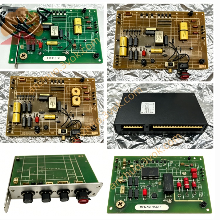
0-57552-4A
Description
II. Model Interpretation
0-: Prefix for Reliance Electric standard products
57552: Core model, representing Universal Drive Controller (UDC)
4: Hardware version (version 4)
A: Revision version / Function upgrade (version A)
III. Technical Parameters
Processor: Microprocessor, for real-time control of AC/DC drives
Memory: 256KB Flash (non-volatile), 512KB SRAM, 4KB dual-port SRAM
Power supply: 230VAC, 50/60Hz
Control capability: Single module controls 2 PMI (Power Module Interface); up to 10 UDCs in a single rack, controlling 20 drives
Size: Approximately 100×90×30mm
Weight: 0.2–0.3kg
Protection level: IP20
Operating temperature: 0–55℃
IV. Interface and Communication Configuration
1. Communication Interface
Fiber optic link ×2: Connect 2 PMIs, transmitting control algorithms and diagnostic data, with strong anti-interference capability
Multibus bus: Rack backplane communication, as a Multibus slave station interacting with the CPU module
2. Input/Output
Analog output ×4: For data recording or external instruments
Status LED ×6: Panel indicator lights, real-time display of power, operation, fault, etc.
V. Core Functions
Multi-axis motion control: Precise control of speed, position, torque, supporting synchronous / linked control
Real-time algorithm processing: Built-in PID and other control algorithms, closed-loop adjustment of drive parameters
Fault diagnosis and protection: Overcurrent, overvoltage, overheat monitoring, fault alarm and recording
Programmable configuration: Users can adapt to different drives and process requirements through software programming
Data acquisition and monitoring: Analog output and fiber optic communication, real-time upload of operation data
VI. Application Scenarios
Industrial automation production lines: Automotive manufacturing, electronic assembly, packaging machinery
Machine tool processing: Multi-axis control of CNC lathes, milling machines, machining centers
Process control: Metallurgy, papermaking, textile, chemical, etc. continuous production equipment
Distributed power system: Large equipment multi-motor collaborative drive scenarios
VII. Usage and Maintenance Instructions
1. Installation
Install on the AutoMax standard rack, fixed in a single slot, ensuring reliable backplane connection
Clean the fiber optic interface to avoid dust contamination; connect the analog output lines properly, with shielding and grounding
2. Programming and Configuration
Use Reliance Electric AutoMax programming software (Manual S-3007)
Configure drive parameters, control mode (speed / position / torque), communication address
3. Daily Maintenance
Regularly check the LED status; troubleshoot if there are abnormalities in the fiber optic connection, power supply, or drive failure
Maintain the rack ventilation, keep the temperature within 0–55℃, avoiding damp and dusty environments
Regularly power on the spare module to prevent Flash data loss
4. Fault Handling
LED fault light on: Prioritize checking the fiber optic link, PMI module, and power voltage
Communication interruption: Investigate Multibus backplane connection, module address configuration
Control anomaly: Re-download the program, verify parameter settings, and check the drive feedback signal
Get a Quote