
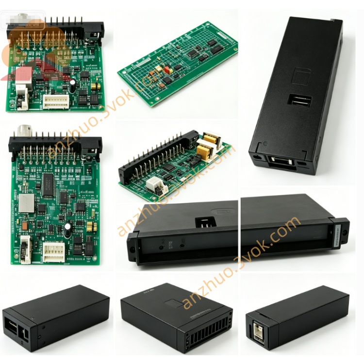
0-57405-D
Description
Model Explanation 0-57405-D
0-57405: Basic Model (AutoMax Drive-level Analog I/O)
D: Hardware Version (Enhanced Edition, replaces -C version)
Full Function Name: Drive Analog I/O Module
Compatibility: Only for AutoMax PLC / DCS 5000 system.
Technical Specifications
Manufacturer: Reliance Electric (Allen-Bradley / Rockwell Automation)
Channel Configuration: 10 channels (5 inputs + 5 outputs)
Signal Range: ±10 VDC or 4–20 mA (software configurable)
Resolution: 12 bits
Isolation: Channel ↔ Backplane 2500 VAC Photoelectric Isolation
Operating Temperature: 0°C ~ +55°C (5°C higher than -C version)
Size: 343 × 203 × 38 mm (1.25" slot)
Weight: Approximately 0.8 kg
Power Consumption: ≤12 W (slightly higher than -C version)
Enhanced Features: Higher anti-interference, optimized thermal design, compatible with -C labels
Interface and Indicator Lights
Backplane: AutoMax专用边缘连接器 (power, address, data)
Frontend: 10-bit screw terminal block (channels 1–10)
Status LED:
OK (Green): Module is running normally
FAULT (Red): Channel / Power / Communication failure
Programming Port: TO PMI (connect to programmer for debugging)
Core Function
Drive Closed-loop Control: Directly drive GV3000 and other inverters to achieve speed / position closed-loop.
Mixed Analog Processing: 5 channels of AI (sensors) + 5 channels of AO (actuators / inverters).
High Precision Conversion: 12-bit resolution, meeting industrial process control accuracy.
Hot Swap: Replace the rack while powered on, without interrupting system operation.
Fault Self-Diagnosis: Fault indicator locates short circuit / open circuit / signal over-limit.
Direct Replacement of -C version: Pins / software fully compatible, no need to modify program or wiring.
Typical Applications
System: Reliance AutoMax (DCS 5000)
Industry: Metallurgy, Papermaking, Water Treatment, Power, Heavy Machinery
Usage: Inverter control, temperature / pressure / flow collection, valve position control, multi-machine synchronization
Installation and Maintenance Installation
After power failure, insert the rack slot and lock the panel; connect ±10V / 4–20mA according to the terminal definitions.
After powering on, the OK light will be on, indicating normal operation. The CPU will automatically identify and assign addresses. Maintenance
Quarterly: Check terminal fastening, LED status, cable shielding and aging.
Half-yearly: Perform power-off anti-static cleaning of terminals and surfaces.
Replacement: 0-57405-D can be directly replaced with 0-57405-C, no need to rewire / modify parameters. Fault diagnosis
OK indicator not lit: Check the power supply of the rack, the contact of the backplane, and whether the modules are securely plugged in.
FAULT indicator lit: Check for wiring short circuits / open circuits, signal over-limitations, and channel damage.
Signal abnormalities: Verify the range configuration, terminal polarity, and shielding grounding.
Get a Quote