
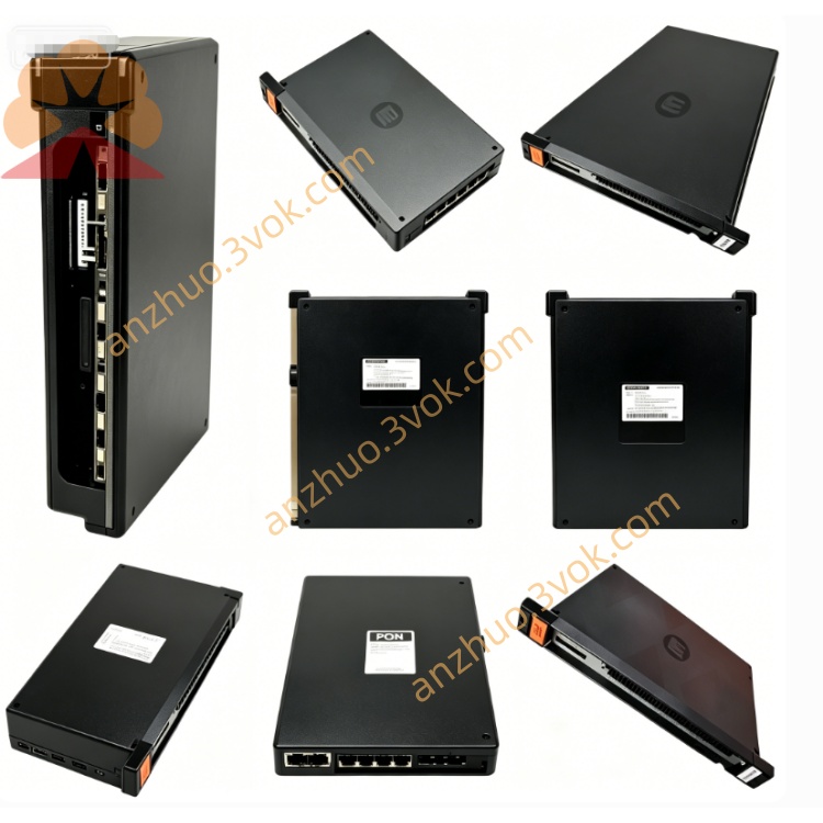
057405-C
Description
Model Explanation 0-57405-C
0-57405: Basic Model (AutoMax Drive Analog I/O)
C: Hardware Version (Standard Edition, different from -E Enhanced Edition)
Alias: 057405C, 57405-C, 57C405
Full Function Name: Drive Analog I/O Module
Compatibility: Dedicated for AutoMax PLC / DCS 5000, not universal.
Technical Parameters
Manufacturer: Reliance Electric (Allen-Bradley / Rockwell Automation)
Module Type: Analog I/O (Analog I/O), dedicated for drive control
Channel Configuration: 10 channels (5 inputs 5 outputs, voltage/current configurable)
Signal Range: ±10 VDC or 4–20 mA (software switch)
Resolution: 12 bits
Isolation: Channel ↔ Backplane Photoelectric Isolation, 2500 VAC
Operating Temperature: 0°C ~ +50°C
Size: 343 × 203 × 38 mm (standard 1.25 inch slot)
Weight: Approximately 0.8 kg
Power Consumption: ≤10 W
Manual Number: D-2715
Interface and Communication Configuration
Backplane: AutoMax Backplane Edge Connectors (Power Supply, Addressing, Data)
Frontend: 10-bit Screw Terminal Block (Channels 1–10 Wiring)
Status Indicators:
OK (Green): Module Normal
FAULT (Red): Channel / Power / Communication Fault
Programming Port: TO PMI Parallel Port (for programmer debugging)
Core Functions
Closed-loop Drive Control: Directly connect to GV3000 and other drives to achieve speed / position closed-loop.
Mixed Signal Processing: 5 Analog Input Channels (Sensors) + 5 Output Channels (Actuators / Frequency Converters).
High Precision Conversion: 12-bit Resolution, suitable for industrial process control accuracy requirements.
Hot Swap: Replace the rack while powered on, without interrupting system operation.
Fault Diagnosis: Fault indicator locates channel short circuit / open circuit / over-limit. Application scenario
System: Reliance AutoMax (DCS 5000)
Industry: Metallurgical rolling, papermaking, water treatment, power, heavy machinery
Application: Frequency converter control, temperature / pressure / flow measurement, valve position control, multi-machine synchronization
Operation and Maintenance Installation
When power is cut off, insert the empty slot and tighten the lock; connect the ±10V/4–20mA signal according to the terminal definition.
When powered on, the OK light turns on indicating normal operation. The CPU automatically identifies and assigns the address. Maintenance
Quarterly: Terminal tightening, LED status, cable shielding / aging inspection.
Half-yearly: Power-off anti-static cleaning of terminals and surfaces.
Replacement: Original 0-57405-C, CPU automatically synchronizes parameters. Fault diagnosis
OK indicator not lit: Check the power supply, backplane, and module connections.
FAULT indicator lit: Check the wiring, signal over-limit, and channel damage.
Signal abnormality: Verify the range, polarity, and shielding grounding. Safety Warning
Power off the equipment, wear an anti-static wristband; use shielded cables for analog signals and keep them away from strong electricity.
Do not plug or unplug the terminal blocks while the equipment is powered on.
Get a Quote