
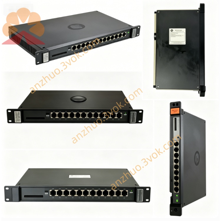
0-57405
Description
Model Explanation
0-57405
0-57405: Basic model (AutoMax analog I/O)
Common suffixes: -C, -E (hardware version)
Alias: 57405, 57C405, 0-57405-C
Full Function Name: Analog I/O Drive Module (Drive Analog I/O Module)
Compatibility: Dedicated for AutoMax PLC / DCS 5000, not usable for other brands of PLC.
Technical Parameters
Manufacturer: Reliance Electric (Allen-Bradley / Rockwell Automation)
Module Type: Analog I/O (Analog I/O), dedicated for drive control
Channel Configuration: 10 channels of analog input/output (voltage/current signals)
Signal Range: Standard ±10 VDC or 4–20 mA (configurable via software)
Resolution: 12 bits
Isolation: Channel-to-backplane logic side photoelectric isolation, withstands 2500 VAC
Operating Temperature: 0°C ~ +50°C
Size: 343 × 203 × 38 mm (standard 1.25-inch slot)
Weight: Approximately 0.8 kg (1.75 lbs)
Power Consumption: ≤10 W
Manual Number: D-2715
Interface and Communication Configuration
Backplane: AutoMax backplane edge connector (power supply, addressing, data exchange)
Front terminal: Screw terminal block (10-channel analog I/O wiring)
Status Indicators:
OK (Green): Module is running normally
FAULT (Red): Fault alarm
Communication: High-speed data exchange between backplane bus and CPU / network module, no independent network port
Core Functions
Analog signal acquisition and output: Processes ±10V/4–20mA signals, suitable for sensors, actuators, and frequency converters.
Drive control dedicated: Directly connects to drive equipment (such as GV3000 series drivers), achieving closed-loop speed/position control.
High-precision data conversion: 12-bit resolution, ensuring industrial process control accuracy.
Hot-swappable support: AutoMax rack can be replaced while powered on, without interrupting system operation.
Fault self-diagnosis: Fault indicator (FAULT) alerts for channel abnormalities, overcurrent, overvoltage, or communication failures. Application scenario
System: Reliance AutoMax (DCS 5000) Distributed Control System
Industry: Metallurgy and steel rolling, papermaking, water treatment, power, heavy machinery, elevators / cranes
Application: Frequency converter control, temperature / pressure / flow signal acquisition, valve position control, transmission system synchronization
Operation and Maintenance Instructions Installation
After power loss, insert the AutoMax rack slot and fasten the front panel latch.
Connect the analog signal (±10V or 4–20mA) according to the terminal definition.
Power on, and the OK light coming on indicates that the module is normal. The CPU will automatically identify and allocate the channel address. Maintenance
Quarterly inspection: Terminal wiring is tightened, LED status, cable shielding and aging.
Half-year maintenance: Power off and clean the terminals and module surfaces with anti-static dry cloth.
Replacement: Use only the original 0-57405 (-C/-E), no need for reconfiguration, the CPU automatically synchronizes parameters. Fault diagnosis
OK light not on: Check the power supply of the rack, the backplane connector, and whether the modules are securely plugged in.
FAULT light on: Check for wiring short circuits / open circuits, signal over-limitation, and channel damage.
Abnormal signal: Verify the range configuration, terminal polarity, and shielding grounding are correct. Safety Warning
Before operation, the power must be turned off. Wear an anti-static wrist strap to prevent static electricity from damaging the analog chips.
The analog cables should use shielded lines and be kept away from strong electricity (such as frequency converters and motors) to avoid EMI interference.
Do not plug or unplug the terminal block while powered on to prevent overcurrent from burning the channel.
Get a Quote