
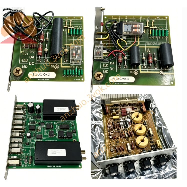
0-57402-F
Description
Model Explanation
0-57402-F: Basic model + Hardware Revision F
Alias: 57402-F, 57C402-F
Full Function Name: 115V AC/DC Low Power Output Module
Compatibility: Limited to AutoMax PLC/DCS 5000 chassis, not compatible with other brands. Technical Specifications
Manufacturer: Reliance Electric (Allen-Bradley/Rockwell)
Number of channels: 16 isolated outputs
Output voltage: 115V AC / 24–115V DC
Current per channel: Maximum 200mA (low power)
Output type: Isolated transistor output (dry contact)
Isolation voltage: 2500Vrms (field ↔ logic side)
Status indication: LED per channel (ON = output activated)
Operating temperature: 0°C ~ +50°C
Size: 343 × 203 × 38 mm (standard 1.25-inch slot)
Weight: Approximately 1.4 kg
Power consumption: ≤ 15W
Interface and communication configuration
Backplane interface: AutoMax backplane edge connectors (power supply, addressing, data)
Field terminals: 36 front panel terminals (16 output channels 0–15 + common / power supply)
Communication: Backplane bus and AutoMax CPU parallel data exchange
Indicators: Module power indicator + 16-channel status indicator
Core functions
Low-voltage digital output: Drive 115V AC indicator lights, 24–115V DC solenoid valves, small relays, etc. for low-power loads.
Electrical isolation protection: 2500Vrms photoelectric isolation, blocking high-voltage noise from entering the PLC.
Independent channel control: 16 output channels can be programmed separately, suitable for multi-point decentralized control.
Hot-swappable support: AutoMax rack can be replaced while powered on, without interrupting system operation.
Status visualization: Real-time display of single-channel LED, facilitating rapid diagnosis. Application scenario
System: Reliance AutoMax (DCS 5000) PLC
Industry: Metallurgy, Papermaking, Water Treatment, Heavy Machinery Automation
Load: 115V AC indicator light, 24V DC solenoid valve, small relay coil, motor starter auxiliary contacts
Operation and Maintenance Instructions Installation
After power loss, insert the AutoMax slot and secure the lock; connect the 115V AC/DC load line according to the terminal numbers; after power on, the CPU will automatically identify the module. Maintenance
Quarterly: Check terminal fastening, LED status, cable aging
Half-yearly: After power outage, clean the module with an anti-static dry cloth
Replacement: Use only the original 0-57402-F, no configuration required, CPU automatically recognizes Fault diagnosis
No output: Check power supply of the load, wiring, channel LED, and program logic.
Malfunction: Check grounding, isolation, shielding, and voltage spikes.
Module not recognized: Reinsert and remove, check backplane connectors and rack power supply. Safety Warning
The terminal strip is equipped with 115V AC high voltage. Power must be disconnected before operation.
Wear an anti-static wrist strap to prevent static damage.
The current of a single channel is ≤ 200mA. Avoid overload and burnout.
Get a Quote