
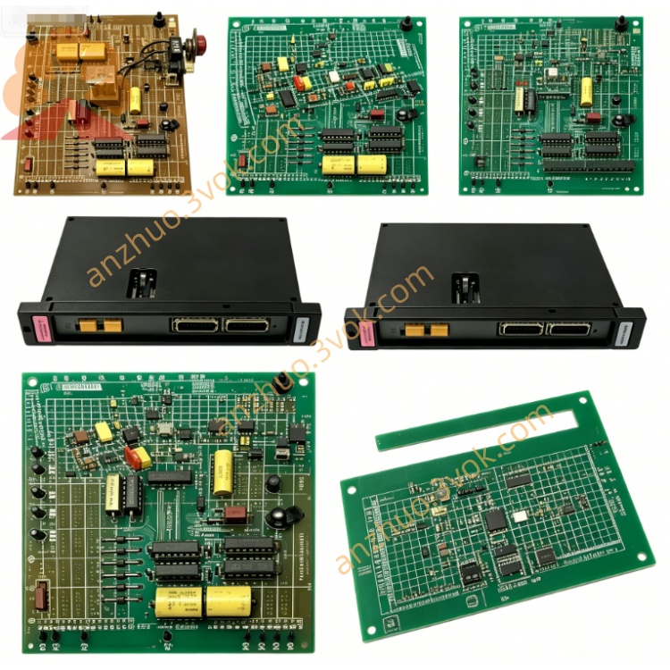
0-57401-1
Description
Model Explanation
0-57401-1: Base part number; 1 denotes a specific hardware revision (compatible with 61C‑501).
Alternate P/N: 57401-1, 57401.
Function Description: 120/240 VAC Digital Input Module (high‑voltage discrete input).
Compatibility: Exclusive to Reliance AutoMax PLC racks; not compatible with other PLC brands.
Technical Parameters
Manufacturer: Reliance Electric (Allen‑Bradley/Rockwell Automation)
Series: AutoMax PLC (Distributed Control System)
Input Voltage: 120–240 VAC (nominal), 85–264 VAC (operating range)
Input Type: Isolated discrete input (dry contact or voltage source)
Number of Channels: 16 isolated input points
Input Impedance: ≥10 kΩ per channel
Response Time: ≤15 ms (ON→OFF, OFF→ON)
Operating Temp: 0°C to +50°C
Dimensions: 13.5 × 8 × 1.5 in (343 × 203 × 38 mm)
Weight: Approx. 1.25 lbs (0.57 kg)
Mounting: Standard AutoMax PLC rack slot (1.25 in width)
Interface & Communication Configuration
Rack Connector: Edge connector for AutoMax backplane (power, data, addressing)
Field Terminals: Screw terminals for 120/240 VAC input wiring (16 channels + common)
Isolation: Optical isolation between field side and logic side (2500 Vrms isolation)
Indicators: LED status per channel (ON = input active)
Backplane Communication: Parallel data bus to AutoMax CPU module
Core Functions
High‑Voltage Signal Acquisition: Converts 120/240 VAC discrete signals to 5V logic for PLC processing.
Electrical Isolation: Protects PLC internal circuits from high‑voltage transients and noise.
Channel Status Monitoring: Provides individual LED indication for each input channel.
Fault Protection: Built‑in surge suppression and overvoltage protection for field wiring.
Rack Integration: Hot‑swappable in AutoMax racks for easy replacement without system shutdown.
Application Scenarios
Equipment: AutoMax PLC systems (Reliance distributed control platform).
Industries: Power generation, oil & gas, metal processing, and heavy machinery requiring 120/240 VAC signal interfacing.
Signals: Limit switches, relay contacts, motor starters, and high‑voltage sensor outputs.
Operation & Maintenance Instructions
Installation
Power OFF the AutoMax rack before installation.
Insert the module into an empty rack slot; secure with front‑panel latches.
Wire 120/240 VAC field signals to the screw terminals (follow channel numbering).
Power ON; verify module recognition via AutoMax CPU and channel LED status.
Maintenance
Quarterly: Inspect terminal connections for tightness; check LED operation.
Semi‑annually: Power OFF, clean the module with dry, lint‑free cloth under ESD protection.
Replacement: Use only original 0-57401-1 modules; no configuration required (auto‑detected by CPU).
Troubleshooting
No Channel LED: Verify 120/240 VAC field power and wiring; check for open circuit.
False Input Triggering: Inspect for voltage transients; verify isolation and grounding.
Module Not Recognized: Check backplane connector seating; verify rack power supply.
Precautions
High voltage present on field terminals; disconnect power before servicing.
Use ESD wristband when handling the module to prevent static damage.
Do not exceed 264 VAC input voltage to avoid module damage.
Get a Quote