
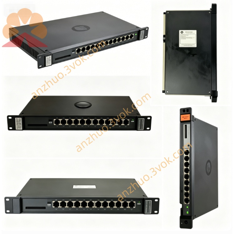
0-57140
Description
Model Explanation
0-57140: Primary part number for the MinPak Plus series regulator board.
Alternate P/N: 802289-10C (Reliance internal drawing number).
It is a dedicated DC drive regulator card, not compatible with Honeywell System 57 or other brands.
Technical Parameters
Manufacturer: Reliance Electric (Allen‑Bradley/Rockwell Automation)
Applicable Drives: MinPak Plus, FlexPak Plus regenerative DC drives
Function: Speed regulation, current loop control, gate drive coupling, fault monitoring
Input Signals: 0–10VDC speed reference, current feedback, armature voltage feedback
Output Signals: Gate drive pulses for SCR bridge, fault relay contact, speed feedback signal
Onboard Potentiometers: Speed gain, current limit, IR compensation, ramp rate
Protection: Overcurrent, overvoltage, field loss, thermal shutdown (via drive logic)
Operating Temp: 0°C to +50°C
Mounting: 3U slot inside MinPak/FlexPak Plus drive cabinet
Weight: Approx. 0.9 kg (2 lbs)
Interface & Communication Configuration
Edge Connector: 24‑pin for drive internal bus (power, I/O, feedback)
Screw Terminals: External speed reference, enable, fault output, ground
Indicators: Power OK, Current Limit, Fault LEDs
Isolation: Opto‑isolated gate drives; surge protection on feedback lines
Core Functions
Closed‑Loop Speed Control: Maintains precise motor speed via armature voltage/ current feedback.
Current Regulation: Controls SCR firing angle to limit motor current and prevent overload.
Regenerative Operation: Enables 4‑quadrant control for motor braking and energy recovery.
Gate Coupling: Isolates and amplifies control pulses to trigger power SCRs.
Fault Detection: Monitors drive status and triggers alarm on overcurrent, field loss, or overtemperature.
Application Scenarios
Equipment: Reliance MinPak Plus / FlexPak Plus regenerative DC motor drives (1–200 HP).
Industries: Cranes, conveyors, extruders, winders, and process lines requiring precise DC speed control.
Installation: Mounted in the drive’s internal 3U slot; compatible with standard 19‑inch rack enclosures.
Operation & Maintenance Instructions
Installation
Disconnect all AC and DC power before installation.
Align the board with the 3U slot and insert firmly; secure with front‑panel screws.
Connect external speed reference, enable, and fault wiring per the drive schematic.
Power ON and verify the PWR LED illuminates; adjust potentiometers for speed and current limit.
Maintenance
Quarterly: Inspect edge connector for dirt/corrosion; verify LED status.
Semi‑annually: Power OFF, clean the board with dry, lint‑free cloth under ESD protection; check potentiometer settings.
Replacement: Use only original 0-57140 (802289-10C) boards; recalibrate speed and current loops after replacement.
Troubleshooting
No PWR LED: Check drive internal 24VDC supply and edge connector seating.
Current Limit LED On: Verify motor load, current transformer wiring, or potentiometer settings.
Drive Fault: Inspect field loss circuit, SCR bridge, or regulator board for damage.
Precautions
High voltage present on SCR and motor terminals; disconnect power before servicing.
Use ESD wristband when handling the board to prevent static damage.
Do not exceed the drive’s rated motor current to avoid regulator board burnout.
Get a Quote