
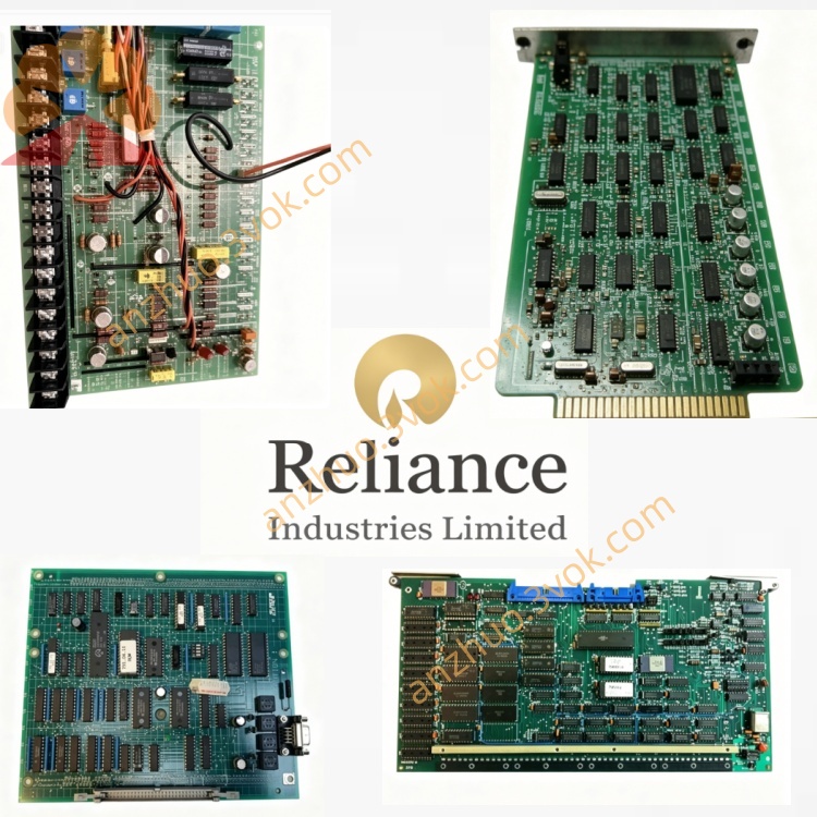
0-57100
Description
Model Explanation
0‑57100: Unique part number for the Reliance FlexPak Plus / Mini‑Pak Plus series preset speed control board.
It is not a Honeywell System 57 card; it belongs to an independent Reliance DC drive system.
Technical Parameters
Manufacturer: Reliance Electric (Allen‑Bradley)
Applicable Drives: Mini‑Pak Plus DC variable‑speed drives
Function: 8‑step preset speed selection, acceleration/deceleration control, logic interlock
Input Signals: Dry contact/24VDC for speed selection; analog 0–10VDC or 4–20mA for external speed trim
Output Signals: Drive logic control, speed feedback, fault relay contact
Potentiometers: 6 onboard for fine tuning speed, ramp, and gain
Protection: Overcurrent, short‑circuit, and thermal protection via drive coordination
Operating Temp: 0°C to +50°C
Mounting: Standard 3U slot or direct mounting inside the drive cabinet
Interface & Communication Configuration
Terminals: Screw terminals for power, speed select, enable, fault, and analog I/O
Connectors: Edge connector for drive internal bus (power and logic)
Indicators: Power ON, Fault, Speed Select status LEDs
Isolation: Inputs optically isolated; surge protection on signal lines
Core Functions
Multi‑speed Preset: Provides up to 8 fixed speed settings selected via external switches or PLC contacts.
Ramp Control: Independently adjustable acceleration/deceleration ramps for smooth speed changes.
Logic Interlock: Enables, inhibits, or coasts the drive based on external conditions.
Speed Trim: Accepts external analog signal to finely adjust the selected preset speed.
Fault Monitoring: Monitors drive status and outputs dry contact alarm signals.
Application Scenarios
Equipment: Reliance Mini‑Pak Plus / FlexPak Plus DC motor drives.
Industries: Conveyors, cranes, extruders, mixers, and process lines requiring multi‑speed DC motor control.
Installation: Mounted inside the drive cabinet or in a adjacent control enclosure.
Operation & Maintenance Instructions
Installation
Ensure drive power is OFF before installation.
Align and insert the board into the designated slot; secure with screws.
Wire external speed select switches, enable, and fault circuits per terminal diagram.
Power ON and verify the PWR LED illuminates; check speed selection and ramp timing.
Maintenance
Quarterly: Inspect terminals for tightness and corrosion; verify LED status.
Semi‑annually: Power OFF, clean the board with dry, lint‑free cloth; check potentiometer settings and edge connector contacts.
Replacement: Use only original 0‑57100 boards; re‑adjust speed and ramp potentiometers after replacement.
Troubleshooting
No Power LED: Check drive internal power supply and edge connector seating.
Speed Not Changing: Verify external switch wiring and potentiometer settings.
Drive Faults: Check fault interlock wiring and drive protection circuits.
Precautions
Disconnect all power before servicing to avoid electric shock.
Use ESD protection when handling the board to prevent static damage.
Do not exceed the rated voltage/current on control terminals.
Get a Quote