
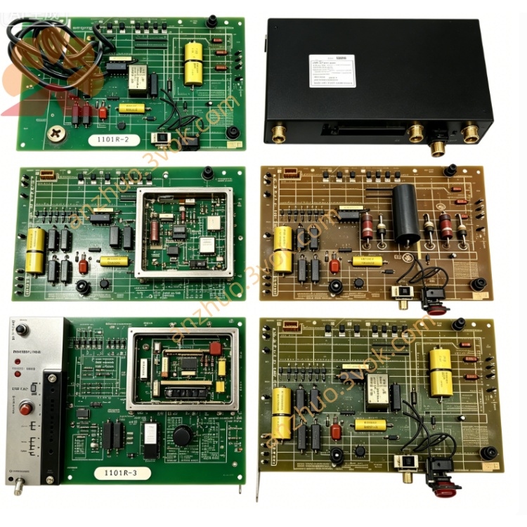
05704-A-0145
Description
Model Explanation
05704: System 57 / 5704 series control card platform
A: Assembly (PCB + components + front panel)
0145: 4‑channel, 4–20 mA analog input control card (vs. 0144 = catalytic sensor input)
Technical Parameters
Manufacturer: Honeywell Analytics (Sieger Limited)
System Compatibility: Honeywell System 57, 5704 series gas detection rack
Channels: 4 independent analog input channels
Input Signal: 4–20 mA (loop‑powered sensors)
Measurement Range: 0–25 mA (linear)
Supply Voltage: 24 VDC ±10% (from rack backplane)
Isolation: 1500 Vrms channel‑to‑backplane isolation
Max Line Resistance: 500 Ω (including sensor)
Operating Temp: −5 °C to +55 °C
Dimensions: 132 × 25 × 172 mm (3U, 1” wide card)
Weight: ~140 g
Key Components: Precision current‑to‑voltage converters, microcontroller, EEPROM, status LEDs, D‑sub connector
Interface & Communication Configuration
Sensor Inputs: 4 × 4–20 mA loop terminals (per channel)
Backplane: System 57 rack bus (power + data)
Front Port: D‑sub 9‑pin for local configuration/service
Communication: Modbus RTU (via system rack to host/PLC)
Indicators: Power, fault, and channel alarm LEDs
Core Functions
4–20 mA Gas Detector Input: Interfaces with standard loop‑powered toxic/combustible gas sensors.
Concentration Monitoring: Converts 4–20 mA to gas concentration values (0–100% LEL or ppm).
Alarm Logic: Configurable low/high alarm, fault, and inhibit per channel.
Isolation & Protection: Galvanic isolation between field sensors and control system; short‑circuit protection.
Data Communication: Sends channel data and status to System 57 controller and higher‑level systems.
Application Scenarios
Equipment: Honeywell System 57 (5704) gas detection control racks
Sensors: 4–20 mA toxic/combustible gas detectors (H₂S, CO, O₂, LEL, etc.)
Industries: Oil & gas, petrochemical, pharmaceuticals, power, water treatment, marine/offshore
Enclosures: 19” rack‑mount (3U), industrial control panels (indoor, non‑hazardous)
Operation & Maintenance Instructions
Installation
Insert into any 1” slot in the System 57 rack (power off).
Secure front panel with two screws (torque 1.5 N·m).
Wire 4–20 mA sensors to channel terminals (observe polarity).
Power on; verify PWR LED on and no FLT LED.
Maintenance
Quarterly: Check LED status; inspect wiring and terminals for corrosion.
Semi‑annually: Verify 4–20 mA scaling and alarm thresholds via service port.
Replacement: Use only original 05704‑A‑0145. Power off rack before removal.
Troubleshooting
No sensor signal: Check 24 VDC loop power, wiring, and sensor continuity.
FLT LED on: Open/short circuit, overrange input, or card fault.
Inaccurate reading: Verify sensor calibration, loop resistance, and scaling setup.
Precautions
ESD Protection: Use anti‑static wristband when handling the card.
Loop Power: Confirm sensor loop voltage (12–24 VDC) before connection.
Calibration: Calibrate sensors annually or after maintenance.
Get a Quote