
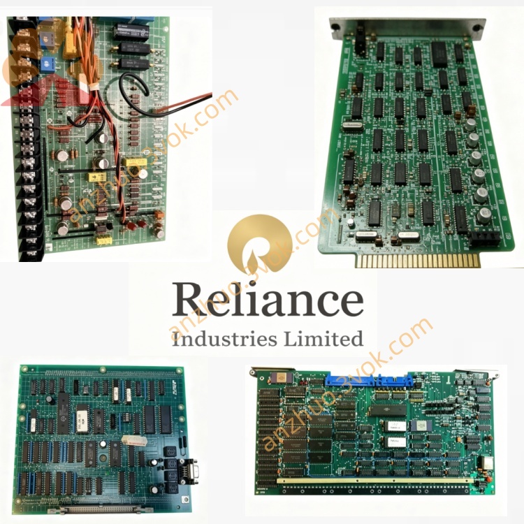
0-57026
Description
Model Explanation
0-57026: Base part number, GV3000 speed control PCB (no revision suffix)
Technical Parameters
Manufacturer: Baldor Reliance (Rockwell Automation)
Compatible Drives: GV3000 series (5–100 HP, 230/460/600 VAC, 50/60 Hz)
Control Signal: 0–10VDC speed reference (min/max adjustable via on-board potentiometers)
Supply Voltage: 24VDC ±10% (from drive control power)
Speed Range: 0–100% of drive rated speed (field adjustable)
Operating Temp: 0°C to +60°C
Dimensions: 190 × 150 × 30 mm
Weight: 1.2 kg
Key Components: Precision potentiometers, signal conditioning op-amps, isolation circuits, status LED
Interface & Communication Configuration
Control Signals: 24VDC power, 0–10VDC speed reference output, enable, ground
Connections: 4-pin terminal block to regulator board; potentiometer access via drive front panel
Core Functions
Min/Max Speed Setting: Sets adjustable lower and upper speed limits (0–100%) for the drive.
Speed Reference Generation: Provides isolated, noise-immune 0–10VDC speed command to the regulator board.
Signal Conditioning: Filters and buffers speed signals to ensure stable motor operation.
Local Speed Trim: Allows on-site adjustment of speed range without drive programming.
Application Scenarios
Equipment: Reliance Electric GV3000 AC drives (5–100 HP, 230/460/600 VAC)
Industries: Conveyors, pumps, fans, packaging, material handling, general manufacturing
Enclosures: NEMA 1, NEMA 4/12
Operation & Maintenance Instructions
Installation
Mount horizontally in the drive control section, near the regulator board.
Secure with two screws (torque 1.8 N·m).
Connect 24VDC power and signal cables to the terminal block.
Route potentiometer wiring to the front panel access hole.
Maintenance
Quarterly: Inspect potentiometers and wiring for wear; clean with low-pressure dry air (ESD precautions).
Semi-annually: Verify torque on connections; test min/max speed adjustment range.
Replacement: Use only original 0-57026. Disconnect power before service.
Troubleshooting
No speed reference: Check 24VDC supply, wiring, and potentiometer continuity.
Unstable speed: Inspect for loose connections, dirty potentiometers, or electrical noise.
Speed limit not changing: Verify potentiometer wiring and regulator board configuration.
Precautions
ESD Protection: Use anti-static wristband when handling the board.
Noise Avoidance: Keep signal cables separated from high-power wiring.
Adjustment: Set min/max speeds with the drive stopped to prevent unexpected motion.
Get a Quote