
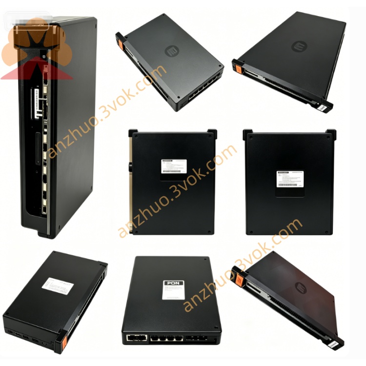
0-56963-A
Description
Model Explanation
0-56963: Base part number, GV3000 power board (15–25 HP)
-A: Revision A, first production version, compatible with 15–25 HP units
Technical Parameters
Manufacturer: Reliance Electric (Rockwell Automation)
Compatible Drives: GV3000 series, 15–25 HP, 230/460 VAC, 50/60 Hz
Input Power: 1-phase / 3-phase, 230VAC or 460VAC
DC Bus Voltage: 325VDC (230VAC input) / 650VDC (460VAC input)
Power Devices: Integrated rectifier bridge, IGBT gate drivers, snubber circuits
Control Supply: 24VDC ±10% (from regulator board)
Protection Features: Overvoltage, undervoltage, overcurrent, short circuit, ground fault, overtemperature
Operating Temp: 0°C to +60°C
Dimensions: 220 × 180 × 35 mm
Weight: 1.8 kg
Key Components: Power rectifier, DC bus capacitors, IGBT inverter, gate drive optocouplers, current/voltage sensors, protection logic
Interface & Communication Configuration
Power Terminals: AC line input (L1/L2/L3), DC bus (+/–), motor output (U/V/W)
Control Signals: 24VDC power, enable, fault reset, current monitor, voltage monitor, overtemperature alarm
Communication: No direct communication; interfaces with regulator board via flat cable for commands and status
Core Functions
AC-to-DC Rectification: Converts AC line power to stable DC bus voltage for the inverter.
IGBT Inverter Control: Drives the IGBT power modules to generate PWM AC output for the motor.
Power Regulation: Maintains DC bus stability under varying load conditions.
Fault Protection: Detects and reacts to overcurrent, overvoltage, short circuit, ground fault, and overtemperature conditions.
Signal Sensing: Provides real-time current, voltage, and temperature feedback to the regulator board.
Application Scenarios
Equipment: Reliance Electric GV3000 AC drives (15–25 HP, 230/460 VAC)
Industries: General manufacturing, material handling, conveyors, pumps, fans, packaging
Enclosures: NEMA 1, NEMA 4/12
Operation & Maintenance Instructions
Installation
Mount horizontally at the bottom of the drive cabinet, below the regulator board.
Secure with four screws (torque 1.8–2.0 N·m).
Connect AC input, DC bus, and motor output cables (torque 2.0 N·m).
Attach flat cable to regulator board for control and sensing signals.
Maintenance
Quarterly: Inspect terminals, cables, and components for wear or damage; clean with low-pressure dry air (ESD precautions).
Semi-annually: Check DC bus capacitors for bulging or leakage; verify torque on all power connections.
Replacement: Use only original 0-56963-A; disconnect and lock out all power, discharge DC bus before service.
Troubleshooting
No DC bus voltage: Check AC input, fuses, rectifier bridge, and regulator board enable signal.
Overvoltage fault: Verify AC line voltage, check for regenerative load, inspect braking resistor (if used).
Overcurrent/short circuit: Check motor winding insulation, motor cables, IGBT modules, and current sensors.
Overtemperature: Inspect cooling fan, heat sink, and ambient temperature; check for blocked ventilation.
Precautions
High Voltage: DC bus can hold 650VDC+ residual voltage; discharge fully before maintenance.
ESD Protection: Use anti-static wristband when handling the board.
Environment: Avoid moisture, dust, corrosive gases, and vibration.
Get a Quote