
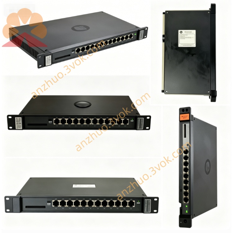
0-56303
Description
Model Explanation
0-56303: Base part number for Reliance Electric’s auxiliary logic board series for GV3000/VZ3000 drives.
Common suffix: -3 (revision 3, latest firmware/component upgrade).
Technical Parameters
Input Voltage: 24VDC ±10% (control power); ±15VDC (analog reference).
Signal Range: 0–10V analog, 4–20mA current loop, 5–24VDC digital I/O.
On-Board Components: 6 blue potentiometers (trimming), 15 Zener diodes, 16+ transistors, 115+ resistors, multi-type capacitors.
Operating Temperature: 0°C to +60°C (derating above 45°C).
Dimensions: 140mm × 190mm × 25mm (5.5” × 7.5” × 1.0”).
Weight: 0.72kg.
Mounting: Four-corner through-hole mounting (screw installation).
Interface & Communication Configuration
Signal Terminals:
Power: 24VDC, GND, ±15VDC reference.
Analog In/Out: 0–10V signal input, 4–20mA current loop output.
Digital I/O: Start/stop, fault reset, alarm output (dry contact).
Trimming Ports: 6 potentiometer adjustment points for gain/offset calibration.
Communication: Hardwired analog/digital interface (no network protocol); connects directly to the main control board (0-56300).
Core Functions
Precision Signal Conditioning: Filters, amplifies, and trims analog signals for accurate speed/torque control; 6 potentiometers for gain/offset calibration.
Auxiliary Logic Processing: Executes secondary control logic (fault interlocking, mode selection, signal validation) to reduce main board load.
Noise Suppression: On-board surge protectors, Zener diodes, and filter components suppress EMI/RFI in high-noise industrial environments.
Drive System Calibration: Enables fine-tuning of drive parameters (speed loop gain, current loop offset) for optimal motor performance.
Application Scenarios
Industrial Drives: Reliance Electric GV3000 (50–500HP) and VZ3000 series AC/DC drives.
Heavy-Duty Motor Control: Steel mills, mining conveyors, cranes, paper machines, and chemical processing lines.
Legacy System Retrofit: Direct replacement for aging 0-56303 series boards in existing Reliance drive installations.
Operation & Maintenance Instructions
Installation
Mount horizontally in a clean, dry control cabinet (avoid dust, moisture, corrosive gases).
Secure with four screws (torque: 0.9–1.1N·m) to prevent vibration damage.
Wire terminals per schematic: Power to 24VDC, Analog I/O to main board/field devices.
Verify grounding and insulation to avoid short circuits and electrical noise.
Maintenance
Quarterly Inspection:
Check for loose connections, burnt components, or capacitor bulging.
Clean dust with low-pressure dry compressed air (<0.5MPa).
Replacement:
Use only 0-56303 or 0-56303-3 original Reliance parts.
Power off drive and confirm zero voltage before replacement.
Troubleshooting:
Signal drift: Adjust potentiometers or check for dirty terminals.
No signal output: Verify 24VDC power and wiring connections.
Fault alarms: Inspect Zener diodes, transistors, or filter capacitors.
Precautions
Static Protection: Wear anti-static wristband during handling to prevent ESD damage.
Environmental Limits: Operate within 0°C–60°C; avoid direct sunlight and heavy vibration.
Power Off First: Disconnect all power before maintenance to avoid electric shock。
Get a Quote