
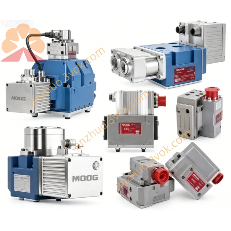
MOOG D634-1011 Direct Drive Servo Valve
D634-1011 belongs to MOOG D634 single stage direct drive servo valve series. It adopts permanent magnet linear force motor structure, equipped with integrated LVDT spool position closed loop feedback and built-in 24VDC drive electronic module. The valve follows ISO 4401 Size 05 installation standard. This model is optimized for balanced dynamic performance, wide temperature adaptability and strong vibration resistance, suitable for long-cycle continuous heavy industrial working conditions.
Description
1. General Description
D634-1011 belongs to MOOG D634 single stage direct drive servo valve series. It adopts permanent magnet linear force motor structure, equipped with integrated LVDT spool position closed loop feedback and built-in 24VDC drive electronic module. The valve follows ISO 4401 Size 05 installation standard. This model is optimized for balanced dynamic performance, wide temperature adaptability and strong vibration resistance, suitable for long-cycle continuous heavy industrial working conditions.
2. Main Features
Single stage direct drive design improves contamination resistance and simplifies hydraulic system structure. Operating performance keeps stable and free from system pressure variation. Built-in EMC compliant electronic circuit reduces external matching parts. Spring centering structure ensures safe reset when power cuts off. Low hysteresis and high positioning resolution guarantee accurate repeated control. This version owns enhanced thermal compensation and reliable running performance under harsh working environment.
3. Application Scope
Applicable to high capacity injection molding machine, die casting equipment, heavy load hydraulic press, metal forming machinery, material fatigue test bench and various high stability required servo hydraulic control systems.
4. Hydraulic Parameters
Installation dimension conforms to ISO 4401 Size 05 standard. Maximum working pressure of pressure port and working ports reaches 350 bar. Return port pressure is limited at 50 bar without external drain port, and can bear 350 bar pressure with drain port connected. Rated flow capacity ranges from 60 to 100 liters per minute under 35 bar pressure difference. Maximum flow reaches 185 liters per minute. Internal leakage is controlled below 0.45 liters per minute.
Applicable working medium is standard mineral hydraulic oil. Allowable fluid viscosity ranges 5 to 400 square millimeters per second, optimal working viscosity is 15 to 100 square millimeters per second. Working fluid temperature ranges from minus 20 degrees Celsius to 80 degrees Celsius. System oil cleanliness shall not be lower than ISO 4406 18/15/12 grade.
5. Control Performance
Full stroke step response time ranges 10 to 14 milliseconds. Hysteresis error is less than 0.4 percent full scale. Control resolution is better than 0.09 percent full scale. Null position drift is less than 0.9 percent under 60 Kelvin temperature change. Negative 3dB frequency response reaches 95 hertz or above.
6. Electrical Parameters
Rated working power supply is 24 volt direct current, allowable voltage fluctuation scope is 18 to 32 volt direct current. Maximum working current is 2.2 ampere. External matched fuse adopts 2.5 amp slow blow type.
Optional control signal modes include positive and negative 10 volt voltage signal, positive and negative 10 milliampere current signal and 4 to 20 milliampere current signal, selected by internal jumper setting. Voltage signal input impedance exceeds 100 kiloohm, current signal input impedance is 50 ohm. Standard 0 to 10 volt spool position feedback signal output is reserved. Electrical interface adopts M18 connector with six signal pins and protective earth terminal, protection grade reaches IP65. Ambient working temperature ranges minus 20 degrees Celsius to 60 degrees Celsius.
7. Working Principle
External analog command signal transmits to integrated electronic unit. The circuit drives linear force motor to push spool displacement. LVDT sensor collects real-time spool position data and sends feedback signal. Control circuit compares target command and actual feedback value, automatically adjusts driving output to realize precise spool position control. Spool displacement changes hydraulic flow area and flow direction, so as to control speed and movement direction of hydraulic actuators.
8. Installation and Connection
Install the valve on smooth flat mounting surface according to standard hole position. Install matched sealing rings and fasten M8 bolts with torque between 8 and 10 newton meter. Avoid extrusion deformation and position deviation during installation.
Correctly connect each oil port, pressure port connects oil supply pipeline, return port connects oil tank, two working ports connect hydraulic cylinder chambers, external drain port connects low pressure return pipeline when necessary. Complete pipeline flushing to reach qualified cleanliness before oil filling.
Adopt shielded twisted pair cable for signal wiring. Pin 1 connects 24VDC positive power, pin 2 connects power ground, pin 3 and pin 4 are command signal terminals, pin 5 serves as enabling terminal, pin 6 outputs position feedback signal, earth terminal keeps reliable grounding.
9. Commissioning and Operation
Check mechanical fastening, pipeline connection and circuit wiring completely before power supply. Confirm power voltage and fluid level meet working requirements. Power on the valve, the device finishes automatic initialization and self inspection. Select corresponding signal mode according to field control requirement. Adjust null position to minimize internal leakage under zero command input.
Input different proportional signals to test running state. Zero command keeps spool at middle position without hydraulic output. Positive full scale signal outputs fluid from port A to port B, negative full scale signal realizes reverse flow control. Feedback signal can monitor real-time spool stroke condition.
10. Maintenance and Fault Handling
Regularly inspect external leakage and wiring tightness every month. Replace filter elements periodically to maintain qualified oil cleanliness. Replace aged sealing parts with original MOOG accessories when leakage occurs. Do not disassemble internal precision components without authorization.
No actuator movement is caused by power failure, circuit breakage or missing command signal, check power loop and signal connection. Slow response results from insufficient pressure, excessive oil viscosity or fluid contamination, adjust working parameters and keep oil quality stable. System vibration and unstable operation relate to electromagnetic interference and mismatched control parameters, optimize shielding grounding and adjust controller gain. Oil leakage failure shall be solved by replacing damaged sealing rings.
11. Product Information
Model: D634-1011Type: Direct Drive Electro Hydraulic Servo ValveMounting Standard: ISO 4401 Size 05Configuration: 24VDC integrated electronics, LVDT closed loop position feedback
All technical specifications are subject to actual product performance, parameters can be updated without prior notice.
Get a Quote