
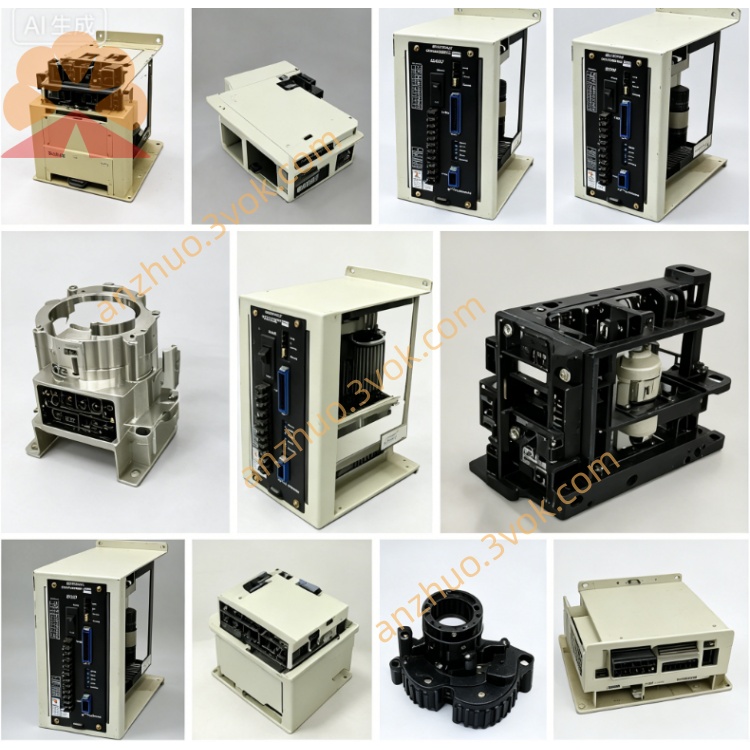
JANCD-MCP02B
Description
II. Technical Specifications
Brand: YASKAWA (Yaskawa)
Model: JANCD-MCP02B (commonly referred to as MCP02B-1)
Power Supply: DC 24V ±10%
Power Consumption: ≤ 28W
Communication Protocols: EtherNet/IP, Profibus-DP, Modbus RTU, RS-485
Network Port Rate: Up to 100Mbps
Operating Temperature: -10℃ to 60℃
Storage Temperature: -20℃ to 80℃
Humidity: ≤ 90% RH (no condensation)
Compatible with Frequency Converters: A1000 Series (5.5kW to 90kW)
Certifications: CE, UL
III. Installation and Wiring Installation
Only for the dedicated slot of the A1000 control cabinet, it must be unplugged before insertion.
Align and push in the guide rail, then lock the fixing screws to ensure good contact with the back panel.
Wiring
Power: Positive and negative poles of the DC24V correspond to the terminals of the board card, and be tightened without loosening.
Communication: Ethernet port connects to PLC / upper computer; RS-485/Profibus terminals connect to the corresponding bus cables.
Grounding: The grounding terminal of the board card is reliably connected to the control cabinet ground to reduce interference.
V. Maintenance and Care
Daily: Observe the LED status lights to confirm normal communication / operation; Keep the cabinet dry and dust-free.
Regularly (every 3 months): Unplug for dust cleaning; Check the connectors for looseness and oxidation; Verify the torque of the wiring terminals.
Long-term: Avoid high temperature, humidity, and vibration environments; Store spare parts in a dry environment of -20℃ to 80℃ with sealing.
VI. Fault Troubleshooting
Communication failure
Check the connection and connector of the network cable / bus cable; Verify the matching of protocol and baud rate parameters.
Observe the communication LED light; If abnormal, replace the cable or board card for testing.
Power failure
Measure the DC24V voltage within ±10% range; Check for short circuits or loose connections between the power module and wiring.
Frequency converter no response
Reinsert the board card to ensure good contact; Check if the back panel is intact; If still abnormal, replace the MCP02B board card.
Data transmission error
Check the grounding for reliability; Investigate on-site electromagnetic interference; Update the communication parameter configuration.
Get a Quote