
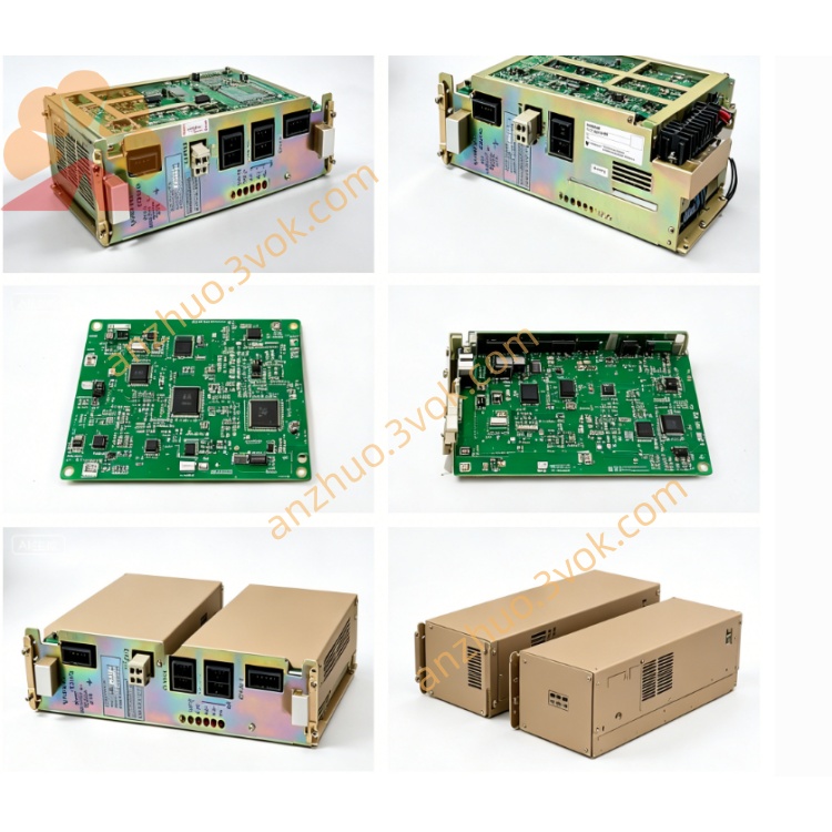
JANCD-MCP01
Description
II. Technical Specifications
Brand: YASKAWA (Yaskawa)
Model: JANCD-MCP01
Power Supply: DC 24V ±10%, ≤ 500mA
Power Consumption: ≤ 25W
Processor: Specialized communication / motion processor
Communication Protocols: EtherNet/IP, Profibus-DP, DeviceNet, Modbus RTU
Network Port Rate: Up to 100Mbps
Operating Temperature: 0~40℃
Storage Temperature: 0~50℃
Humidity: ≤ 80% RH (no condensation)
Weight: Approximately 1.15kg
Dimensions: 144×72×250mm (H×W×D)
Certifications: CE, UL
III. Installation and Wiring Installation
Only for use in the CPU rack slots of XRC/MRC control cabinets, for disconnection and insertion under power off conditions.
Align with the guide rail and push in smoothly. Tighten the locking screws to ensure a secure fit against the back panel (JANCD-MBB10). Connecting the wires
Power Supply: DC24V, positive and negative poles correspond to the power terminals of the board card, and there is no looseness.
Communication: Ethernet port connects to PLC / upper computer; Profibus-DP/DeviceNet terminals correspond to the bus cables; RS-485 connects to Modbus devices.
Grounding: The grounding terminal of the board card is reliably connected to the ground of the control cabinet to reduce interference.
V. Maintenance and Care
Daily: Observe the LED status lights every day to confirm normal operation / communication; Keep the cabinet dry and dust-free.
Regularly (every 3 months): Power off and blow off the dust from the board card; Check if the connectors are not loose or oxidized; Verify the torque of the terminal blocks.
Long-term: Avoid high temperature / humidity / vibration environments; Store the spare board card sealed and at a temperature of 0 - 50℃ and dry.
VI. Fault Troubleshooting
Communication Failure
Check the connection of the network cable / bus cable and the connector for damage; Verify the protocol and baud rate match.
Observe the status of the communication LED light; If abnormal, replace the cable or board card for testing.
System Error (such as 0950 CPU error)
Power off and reinsert the board card to ensure good contact in the slot; Check if the backplane JANCD-MBB10 is intact.
If still an error, replace the MCP01 board card.
Power Supply Abnormal
Measure if the DC24V voltage is within ±10% range; Check if there is a short circuit or loose connection between the power module and the wiring.
I/O No Response
Check the I/O wiring terminals; Confirm that the board card I/O configuration parameters are correct; Restart the system or replace the board card.
Get a Quote