
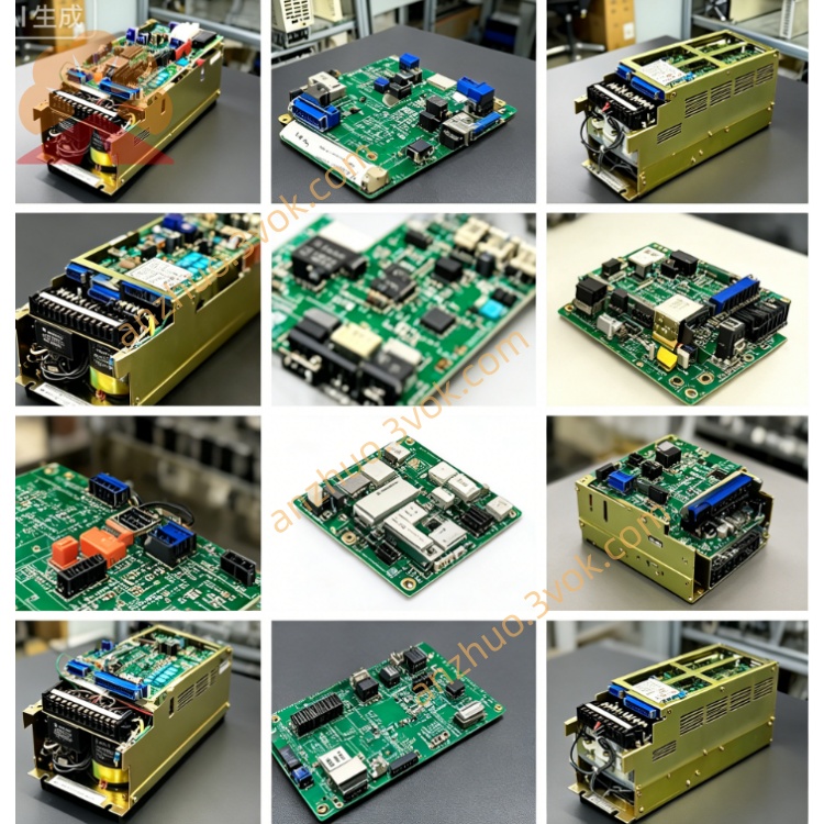
JANCD-JSP11
Description
I. Product Introduction
Brand: Yaskawa (Yaskawa)
Model: JANCD-JSP11 (Sub-model: JSP11-1, Revision B01)
Part Number: DF9202532-B0
Series: YASNAC J300 (Compatible with JCP10, JIF10, JMM01)
Function: Analog spindle control + Encoder position feedback + Positioning signal processing
Alias: J300 old spindle board, SP11 spindle control baseboard, Analog spindle board
Core purpose:
Control analog spindle (0–10V command), up to 12000 rpm
Receive incremental encoder (A/B/Z phases) feedback to achieve speed closed-loop and direction
Output spindle direction, gearshift, brake control signals
Compatible with early CNC lathes, vertical machining centers, drilling machines
II. Technical Specifications
1. Control Specifications
Spindle command output: Analog DC 0–10V, resolution 10bit, accuracy ±1.0%
Encoder feedback: Incremental A/B/Z phases, 5V differential, supports 1024–4096 ppr
Highest response frequency: 500kHz (incremental)
Control mode: Speed closed-loop, spindle direction (positioning accuracy ±0.1°)
2. Interface Terminals
CN1: Spindle command 0–10V + Enable / Fault I/O
CN2: Encoder feedback (A/B/Z, 5V differential)
CN3: Backplane bus (40-pin), connects JCP10 main control board
CN4: Spindle direction / Gearshift output (relay contacts, 250VAC/2A)
3. Electrical and Environmental
Power Supply: DC24V ±10%, power consumption approximately 10W
Size / Weight: Approximately 245×210×25mm, weighs 1.5kg
Operating Environment: Temperature 0–50℃, humidity 30%–85% (no condensation)
Isolation Voltage: I/O and system side AC1000V/1min
LED Indicators: PWR (Power), RDY (Ready), ERR (Fault), ENC (Encoder)
III. Differences from JSP02/JSP04
JSP11: Old analog spindle board, 0–10V, single axis, basic positioning, economy type
JSP02: Upgraded analog spindle board, higher accuracy (±0.5%), more stable direction
JSP04: MECHATROLINK-III bus, 4-axis联动, high-precision positioning, high-end application
IV. Installation and Wiring Tips
Installation: J300 cabinet Slot 4 (spindle slot), anti-static, clean gold fingers.
Wiring: CN1 analog use shielded wire, single-ended grounding; CN2 encoder differential line should be away from power lines.
Self-check: Normal operation when PWR is constantly on, RDY flashes, ERR extinguishes.
Common Alarms:
ALM30: Backplane communication failure → Check CN3 cable, JCP10 power supply
ALM31: Encoder abnormal → Loose wiring, insufficient 5V power supply, encoder damage
ALM32: Spindle command abnormal → CN1 short circuit, analog output chip failure
Get a Quote