
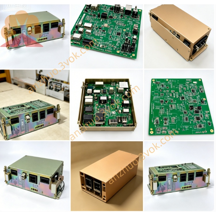
JANCD-JSP02
Description
I. Product Introduction
Brand: Yaskawa (Yaskawa)
Model: JANCD-JSP02 (Revised Version: -1/-2)
Part Number: DF9202611-A
Series: YASNAC J300 (Complementary JCP10 main control board, JIF03/JIF10 I/O board, JMM01 storage board)
Function: Spindle speed / position control + encoder feedback interface
Alias: J300 spindle board, SP02 spindle control baseboard, positioning feedback board
Core purpose:
Control analog/digital spindle (0–10V or RS-485 commands), supports 0–20000 rpm speed adjustment
Receive spindle encoder (incremental / absolute) feedback to achieve position closed-loop and orientation
Output spindle orientation, gear shift, clutch control signals
Suitable for spindle control requirements of lathes, machining centers, drilling and tapping centers, etc.
II. Technical Specifications
1. Control Specifications
Spindle command output: Analog DC0–10V (±10V optional), resolution 12bit, accuracy ±0.5%
Encoder feedback: Supports incremental (A/B/Z phases, 5V/24V) or absolute (SSI/BiSS)
Highest response frequency: 1MHz (incremental), supports 1024–8192 ppr encoder
Control mode: Speed closed-loop, position closed-loop, orientation positioning (orientation accuracy ±0.01°)
2. Interface Terminals
CN1: Spindle command output (+/-10V/0–10V) + Enable / Fault I/O
CN2: Encoder feedback (A/B/Z, 5V differential / 24V single-ended)
CN3: Backplane bus (40-pin, connects JCP10) + DC24V power supply
CN4: Spindle orientation / gear shift output (relay contacts, 250VAC/3A)
3. Electrical and Environmental
Power Supply: DC24V ±10%, power consumption approximately 12W
Size / Weight: Approximately 245×210×25mm, weight 1.8kg
Operating Environment: Temperature 0–55℃, humidity 30%–85% (no condensation)
Isolation Voltage: I/O and system side AC1500V/1min, analog quantity and digital quantity isolation
LED Indicators: PWR (power), RDY (ready), ERR (fault), ENC (encoder), SPD (speed)
III. Installation and Wiring
1. Installation
Power off and discharge for ≥5 minutes, anti-static operation.
Insert J300 cabinet Slot 4 (spindle dedicated slot), adjacent to JCP10.
Fix screws with torque 1.0–1.5N·m to ensure good contact of gold fingers.
Power on self-check: PWR constantly on, RDY flashing, ERR off.
2. Wiring Points
CN1 (Spindle command): 0–10V to frequency converter / servo spindle, GND common ground, avoid interference.
CN2 (Encoder): Differential signal use shielded twisted pair, shield layer single-ended grounding (control cabinet side).
CN4 (Orientation output): Relay contacts connected to spindle clutch / brake, external add rectifier diode.
Do not plug or unplug terminals and backplane cables while powered on to prevent board damage.
IV. Fault Troubleshooting
1. Common Alarms (display on panel)
ALM30 (ERR constantly on): Backplane communication failure → Check CN3 cable, JCP10 power supply, gold fingers oxidation.
ALM31 (ERR flashing): Encoder abnormal → Check wiring, power supply, encoder damage, frequency exceeds limit. ALM32 (ERR Slow Blinking): Main spindle command error → Check CN1 wiring, analog output failure, load short circuit.
ALM33 (ERR Blinking 3 Times): Directional positioning failure → Check CN4 relay, mechanical jamming, parameter error.
2. No spindle speed feedback
Check the power supply (5V/24V) of CN2 encoder.
Use an oscilloscope to detect the pulses of A/B phases and confirm the normal output of the encoder.
Clean the terminals of CN2 and check if they are oxidized or loose.
Replace the JSP02 board card and confirm if the original board feedback circuit is damaged.
Get a Quote