
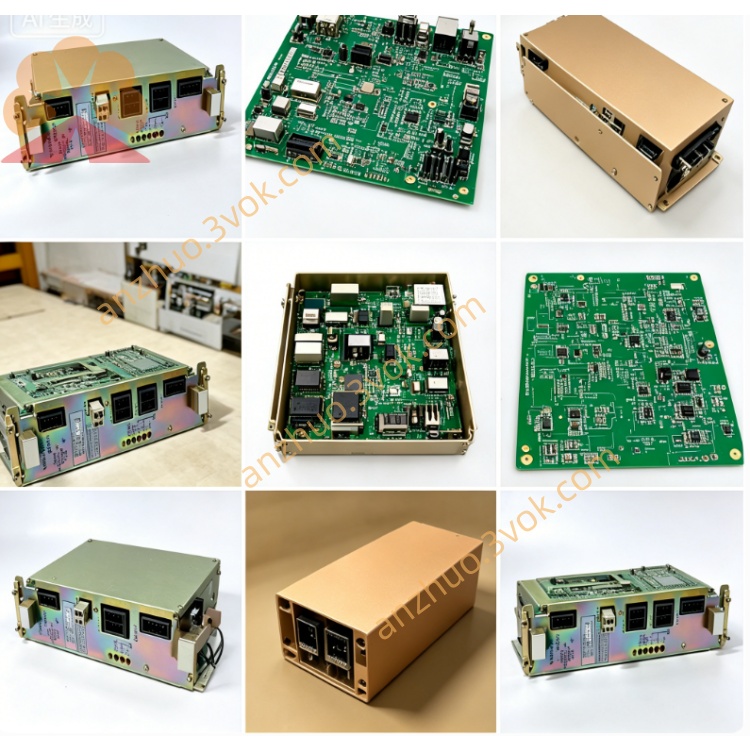
JANCD-JMM01
Description
I. Product Introduction
Brand: Yaskawa (Yaskawa)
Model: JANCD-JMM01 (Revised versions: -1/-2/-3/-4)
Part Number: DF9202411-A (Corresponding to different versions)
Series: YASNAC J300 (Complementary to JCP10 main control board, JIF03/JIF10 I/O boards)
Function: System file storage board (program / parameters / tool / PLC data power-off preservation)
Alias: J300 FILE board, data storage substrate, FLASH storage board
Version differences (capacity):
JMM01-1: 1MB SRAM (program / parameters)
JMM01-2: 2MB SRAM (program / parameters)
JMM01-3: 640MB file area + 2MB FLASH (program / parameters / backup)
JMM01-4: 512MB file area + 2MB FLASH (program / parameters / backup)
Main purpose:
Store CNC processing programs (maximum support 512MB/640MB program library)
Save system parameters, tool compensation, coordinate system, macro programs
Store PLC programs and ladder diagrams, support online reading, writing and backup
Power-off data retention (battery backup or FLASH non-volatile storage)
II. Technical parameters
Storage medium:
-1/-2: High-speed SRAM (battery backup, power-off preservation)
-3/-4: SRAM (2MB) + FLASH (512MB/640MB, non-volatile)
Data retention:
SRAM: DC3.6V lithium battery (life ≥ 5 years)
FLASH: Permanent storage (no battery required)
Read-write interface: J300 dedicated backplane bus (40-pin), connected to JCP10
Data rate: Bus throughput 50MB/s, program read/write ≤ 10ms
Power supply: DC24V (backplane power supply, power consumption approximately 8W)
Size / Weight: Approximately 245×210×20mm, weight 1.5kg
Operating environment: Temperature 0–55℃, humidity 30%–85% (no condensation)
LED indication: PWR (power), RDY (ready), ERR (fault), BAT (low battery voltage)
III. Installation and Wiring
1. Installation
Power off and discharge (≥ 5 minutes), anti-static operation.
Insert into the storage dedicated slot (Slot 1) of the J300 cabinet, adjacent to JCP10.
Push the board evenly, tighten the upper and lower fixing screws (torque 1.0–1.5N·m).
Power on self-check: PWR constantly on, RDY flashing, ERR off, BAT normal.
2. Wiring (no external wiring, only backplane connection)
CN1 (backplane): 40-pin flat cable connects to JCP10 to achieve communication and power supply.
Battery (-1/-2 version): Built-in 3.6V lithium battery, no external wiring required.
IV. Maintenance and Care
1. Daily maintenance (monthly)
Check BAT indicator light: Off is normal, constantly on requires battery replacement (for -1/-2 version).
Visual inspection of the board without bulging, leakage, and connectors without loosening.
2. Regular maintenance (every 6 months)
Battery replacement (for -1/-2 version): Power off and replace 3.6V lithium battery to avoid data loss.
Data backup: Perform program / parameters / PLC program backup to USB drive through the system panel.
Gold finger cleaning: Wipe the backplane gold fingers with alcohol without water to remove oxide layer.
3. Long-term shutdown (> 3 months) Complete backup of system data (programs + parameters + PLC).
- Version 1/2: Ensure sufficient battery power or remove the battery for storage.
V. Fault Troubleshooting
1. Common Faults
ERR constantly lit: Backplane communication failure → Check CN1 cable, JCP10 power supply, and gold fingers for oxidation.
BAT constantly lit (Version 1/2): Low battery voltage → Replace with a 3.6V lithium battery.
Program loss: Battery failure (Version 1/2) or FLASH damage (Version 3/4) → Restore backup data.
Unable to read/write program: Backplane bus failure, board card damage → Replace JMM01 board card.
2. Data Recovery
Pre-Backup: Regularly back up programs/parameters to a USB drive.
After Loss: Restore backup data via USB drive or re-import from the original machine program.
Get a Quote