
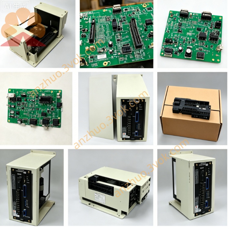
JANCD-JIF03
Description
I. Product Introduction
Brand: Yaskawa (Yaskawa)
Model: JANCD-JIF03 (common suffix: -2 indicates an upgraded revision)
Series: YASNAC J300 (paired with JCP10 main control board, JCP04/05/06 motion boards)
Function: I/O signal interface board (digital input/output, external interlock, signal conversion for machine operation panel)
Status: Factory discontinued, part number DF9202311-C, dependent on second-hand / repair replacement
Alias: J300 I/F Board, General I/O Baseboard
Core purpose:
Complementary to the J300 system, used for external signal interaction of machining centers, lathes, milling machines, etc.
Processes switch quantity signals such as emergency stop, limit stop, reference point, cooling pump, lubrication pump, spindle start/stop, etc.
Expands system I/O points, compatible with machine operation panels, external relays, sensor connections
Different from JCP series:
JCP04/05/06: Motion control board (trajectory interpolation, servo linkage)
JCP10: System main control board (manages PLC, programs, system scheduling)
JIF03: I/O interface board (manages external switches / sensors / actuators signals)
All three are essential components of the J300 standard configuration.
II. Technical Specifications
I/O Points: 32 digital inputs, 32 digital outputs (optically isolated)
Input Signals: DC24V active / passive compatible, response time ≤ 1ms, supports normally open / normally closed
Output Signals: DC24V/0.5A transistor output, maximum load 12W / point, overcurrent protection
Interface Terminals: CN1 (input terminal block, 32 pins), CN2 (output terminal block, 32 pins), CN3 (backplane bus, 40 pins)
Bus Communication: J300 dedicated backplane bus, interacts with JCP10 main control board, data throughput 50MB/s
Power Supply: DC24V (backplane power supply, power consumption approximately 15W)
Size / Weight: Approximately 245×210×25mm, weighs 2.0kg
Operating Environment: Temperature 0–55℃, humidity 30%–85% (no condensation), altitude ≤ 1000m
Isolation Voltage: I/O isolated from system side AC1500V/1min, anti-electromagnetic interference
LED Indicators: PWR (power), RDY (ready), ERR (fault), IN01–IN32 (input status), OUT01–OUT32 (output status)
III. Installation and Wiring (Brief)
1. Installation
After power-off and discharge, insert J300 cabinet I/O dedicated slot (Slot 2), tighten the fixing screws.
Power-on self-check: PWR constantly on, RDY flashing, ERR off.
2. Wiring
CN1 (input): Connect emergency stop, limit stop, reference point, operation panel buttons (DC24V).
CN2 (output): Connect cooling pump, lubrication pump, spindle relay, indicator lights (DC24V).
CN3 (backplane): 40-pin flat cable connects to JCP10 main control board, communication and power supply.
IV. Maintenance and Fault Troubleshooting (Brief)
1. Maintenance
Monthly dust cleaning, check no looseness of terminals, no oxidation of solder joints.
Every 6 months tighten terminals, back up system I/O parameters.
2. Common Faults
ERR constantly on: Backplane communication failure → Check CN3 cable, JCP10 power supply.
No response from input: DC24V power supply abnormal, terminal looseness, optical isolation damage.
Output does not actuate: Short circuit of load, output transistor burned out, parameter configuration error.
Get a Quote