
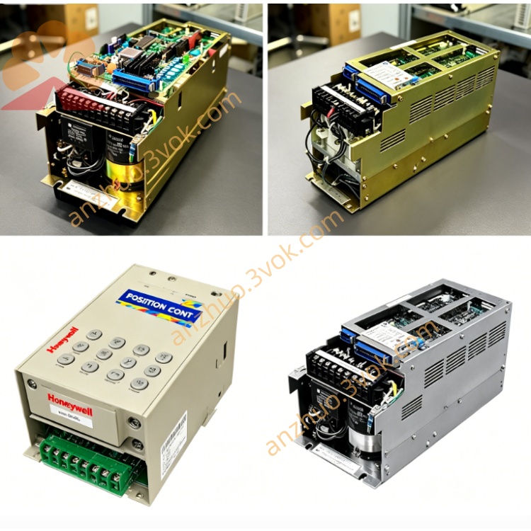
JANCD-JCP10
Description
I. Product Overview
Brand: Yaskawa (Anson)
Model: JANCD-JCP10-1 / JCP10-4 (Common suffixes: -1 standard version, -4 upgraded revision)
Part Number: DF9202024-B0 (JCP10-4)
Series: YASNAC J300 (J30 upgraded version, mid-to-high-end CNC platform)
Function: System main control CPU board (responsible for PLC, program management, logic control, communication between motion boards)
Status: Factory discontinued, no direct replacement available, relies on second-hand / repair replacement
Alias: J300 CPU Board, ACGC Board (with 4M Flash/0.5M RAM)
Core purpose:
Complementary to the J300 system, used for system management of machining centers, lathes, milling machines, etc.
Perform PLC ladder diagram operations, G/M code parsing, parameter storage, human-machine interface interaction
Communicate with the motion board (JCP04/05/06), allocate motion tasks and synchronize axis actions
Differences from JCP04/05/06:
JCP04/05/06: Motion control board (handles interpolation, trajectory, servo synchronization)
JCP10: System main control board (handles PLC, programs, system scheduling, logic)
Both are necessary components for the J300 system, indispensable.
II. Technical Parameters
Processor: 32-bit system CPU, main frequency 200MHz
Memory: 0.5MB RAM (data cache), 4MB Flash (system / program storage)
PLC performance: Ladder diagram operation cycle ≤ 0.2ms, supports 1024 points I/O
Bus interface: J300 dedicated backplane bus (connects motion board / IO board), 50MB/s
Communication ports: RS-232×1 (program transmission), MDI keyboard interface ×1, display unit interface ×1
Power supply: DC24V (backplane power supply, power consumption approximately 25W)
Size / Weight: Approximately 245×210×30mm, weighs 2.3kg (5 lbs)
Operating environment: Temperature 0–55℃, humidity 30%–85% (no condensation)
Protection mechanism: Overcurrent / overvoltage / overheat / data verification error / communication abnormal self-diagnosis
III. Installation and Wiring
1. Installation (backplane slot of the cabinet)
Power off and wait for capacitor discharge (≥5 minutes), anti-static operation.
Align with the J300 cabinet CPU dedicated slot (Slot 1) (motion board in Slot 0).
Push in evenly, tighten the upper and lower screws (torque 0.8–1.2N·m).
Self-check upon power-on: PWR constantly on, RDY flashing, ERR off.
2. Wiring (4 key interfaces)
CN1 (backplane bus): 40-pin flat cable → J300 backplane (connects motion board / JCP06, IO board)
Requirements: Length ≤ 30cm, connector locked, avoid bending
CN2 (display unit): Special cable → J300 operation panel (LCD/MDI)
CN3 (RS-232): 9-pin serial port → computer / USB drive (program upload/download)
CN4 (keyboard / MDI): 20-pin interface → machine operation keyboard
3. Wiring points
All cables should be away from power lines (≥20cm), avoid interference.
Shield layer of the serial port cable is grounded at one end (on the cabinet side).
Do not plug or unplug while powered on, must power off and discharge before operating.
IV. Maintenance and Care
1. Daily maintenance (monthly) Dust removal: Blow the boards, heat sinks, and gold fingers with dry compressed air (0.4–0.6 MPa).
Visual inspection: Capacitors should have no bulging or leakage, solder joints should be free of oxidation, and connectors should be securely connected.
Backup: Back up the system parameters, PLC program, and processing program to a USB drive.
2. Regular maintenance (every 6 months)
Backup batteries: Replace the CR2032 3V battery of the board card (replace within ≤ 5 minutes after power loss to prevent parameter loss).
Connector tightening: Tighten all connection terminals and the screws fixing the board card.
Heat dissipation check: The cabinet fan should be normal, the air duct should be unobstructed, and the environmental temperature should be ≤ 55℃.
3. Long-term shutdown (> 3 months)
Before power off, fully back up data (parameters + programs + PLC).
Remove the backup battery to prevent leakage corrosion.
Dry the cabinet, humidity should be < 60%.
Get a Quote