
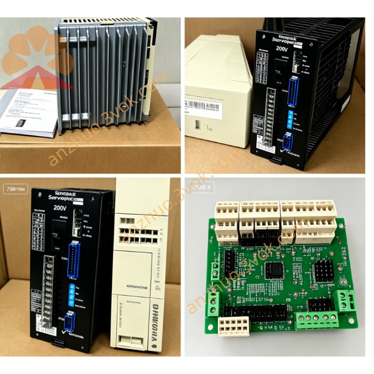
JANCD-JCP06
Description
I. Product Overview
Brand: Yaskawa (Anson)
Model: JANCD-JCP06-1 (abbreviated as JCP06)
Series: YASNAC J300 (J30 upgraded model, high-speed machining flagship)
Function: Motion control CPU board (not PLC board; PLC board is JCP02B)
Status: Factory discontinued, part number DF9202312-C0G, relies on second-hand / repair replacement
Alias: J300 Type B Motion Board (S-HSC high-speed version)
Core purpose:
Up to 8-axis linkage control for high-end milling machines, high-speed machining centers, and turning-milling compound machines
Nanometer interpolation (straight line / arc / spline / helix), spindle + servo axis synchronization, high-speed rigid tapping
System bus management, servo communication, I/O logic coordination, high-speed data processing
Comparison with JCP04/JCP05:
JCP04: Standard type, 6 axes, basic interpolation, ordinary processing
JCP05: High-speed type, 8 axes, operation ≤ 0.1ms, high-speed machining
JCP06: Ultra-high-speed high-precision type, 8 axes, operation ≤ 0.08ms, nanometer interpolation, suitable for precision / high-speed machines
II. Technical Parameters
Processor: 32-bit high-speed motion CPU, operation cycle ≤ 0.08ms (20% faster than JCP05)
Control axes: Maximum 8-axis linkage (including servo axes + spindle, supports dual spindles)
Servo interface: MECHATROLINK-II bus, 100Mbps high-speed communication, compatible with Yaskawa Σ-II/Σ-III servos
System bus: J300 dedicated backplane bus, data throughput 150MB/s (50% improvement over JCP05)
I/O connector: CN3×1 (emergency stop / limit / reference point), CN2×1 (backplane bus), CN1×1 (servo bus)
Power supply: DC24V (backplane power supply, power consumption approximately 40W)
Size / Weight: Approximately 245×210×35mm, weight 2.6kg
Operating environment: Temperature 0–55℃, humidity 30%–85% (no condensation), altitude ≤ 1000m
Protection mechanism: Overcurrent / overvoltage / overheat / communication abnormality / data verification error self-diagnosis + hardware protection
Precision support: Nanometer interpolation (minimum movement unit 0.001μm), high-speed forward control (up to 100 segments)
III. Installation and Wiring
1. Installation (backplane slot in cabinet)
Power off and wait for capacitor discharge (≥ 5 minutes) to prevent static damage to the board.
Align with the Motion dedicated slot (Slot 0) of the J300 cabinet, align the gold fingers.
Push in evenly, tighten the upper and lower fixing screws (torque 0.8–1.2N·m), ensure reliable contact.
Power-on self-check: PWR constantly on (power normal), RDY flashing (standby), ERR off (no fault).
2. Wiring (3 key interfaces, error-proof design)
CN1 (servo bus interface, on the right): MECHATROLINK-II dedicated shielded cable → servo amplifier (Σ-II/Σ-III)
Pins: 1-SG (ground), 2-TX+, 3-TX-, 4-RX+, 5-RX-, 6-24V (power supply)
Requirements: Cable length ≤ 50m, shielded layer single-ended grounding (on the cabinet side), away from power lines (≥ 20cm) CN2 (System Bus Interface, Middle): 40-pin flat cable → J300 Backplane (connecting PLC board / JCP02B, I/O board, display unit)
Requirement: Cable length ≤ 30cm, avoid bending, lock the connector
CN3 (I/O Signal Interface, Left): 20-pin terminal block → External emergency stop, limit, reference point switch
Key signals: EMG (Emergency Stop, Normally Closed), LIMIT+/- (Positive and Negative Limit, Normally Closed), REF (Reference Point, Normally Open)
Requirement: Signal lines use 0.75–1.0mm² copper wire, emergency stop circuit is independently powered, shield layer is grounded
3. Wiring Prohibitions
Prohibit the parallel laying of servo bus and power lines to avoid electromagnetic interference.
Prohibit sharing the terminal block for 24V power supply lines and signal lines to prevent short circuits.
Prohibit plugging and unplugging connectors while powered on; it must be powered off and discharged before operation.
IV. Maintenance and Care
1. Daily Maintenance (once a month, powered off operation)
Clean and dust off: Use dry compressed air (0.4–0.6MPa) to blow the surface of the board card, heat sink, and gold fingers, especially cleaning the areas with accumulated dust (to avoid overheating).
Visual inspection: Capacitors should have no bulging / leakage, solder joints should have no oxidation / short circuit, connectors should not be loose / rusted, gold fingers should have no scratches / oxidation.
Data backup: After powering on, execute system parameters, processing programs, tool compensation backup to the USB drive (to prevent data loss).
2. Regular Maintenance (once every 6 months, powered off operation)
Backup battery replacement: Replace the SRAM backup battery of the board card (CR2032, 3V), powered off replacement ≤ 5 minutes (timeout will lose parameters), after replacement, re-power and restore backup parameters.
Connector tightening: Re-tighten all connection terminals of CN1/CN2/CN3 with the board card fixing screws to prevent vibration loosening.
Heat dissipation system inspection: Confirm that the cabinet fan is running normally, the air duct is not blocked, and the heat sink is not dusty (excessive environmental temperature will trigger overheating alarm).
Insulation test: Use a 500V megohmmeter to measure the insulation resistance between the board card and the cabinet ground, ≥ 1MΩ is qualified (wetted requires drying treatment).
3. Long-term Shutdown (> 3 months)
Before powering off, **fully back up system data (parameters + programs + compensation)** to the USB drive and dual-back up to the computer.
Remove the SRAM backup battery to prevent leakage corrosion of the circuit board.
Place desiccant in the cabinet to keep humidity < 60%, to avoid oxidation due to moisture.
Before reactivating: Dry for 24 hours, install a new battery, power on to restore parameters, test without abnormalities before powering on.
V. Fault Troubleshooting
1. Common Fault Codes (displayed on the CNC panel, corresponding to the ERR light status of the board card)
ALM01 (ERR constantly on): Motion board not ready
Check: Is the DC24V power supply normal, is the CN2 backplane connection loose, is the PWR light off, are the board card gold fingers oxidized (try again after cleaning)?
ALM02 (ERR flashing): Servo communication abnormal
Check: Is the CN1 servo cable damaged / loose, is the shield layer grounded, is the servo amplifier power normal, are the communication parameters matched (baud rate / address)?
ALM03 (ERR flashing slowly): Overheating alarm
Check: Is the heat sink dusty, is the cabinet fan stopped, is the environmental temperature > 55℃, is the board card overloaded (test with reducing the number of simultaneously linked axes)?
ALM04 (ERR flashing 4 times): Axis limit exceeded
Check: Is the CNC parameters set axis number > 8, is the servo axis configuration duplicated, is the backplane bus conflicting? ALM05 (ERR flashes 5 times): SRAM data error
Check: Is the backup battery dead? / Is there leakage, is the power-off duration too long, or are the parameters damaged (replace the battery and restore the backup parameters)?
ALM06 (ERR flashes 6 times): Interpolation operation error
Check: Is there any error in the processing program (such as illegal G codes), are the servo parameters matched (electronic gear ratio), or is the board card aged (replace and test)?
2. No display / No startup (PWR light not on)
Check the total power supply of the cabinet and the output of the DC24V switching power supply (measure the voltage with a multimeter).
After power loss, unplug the JCP06 board card, wipe the gold fingers with isopropyl alcohol, dry them, and reinsert them.
Replace the same model normal board card and confirm if the original board is damaged (if damaged, repair or replace is required).
3. Abnormal movement (jitter, inaccurate positioning, processing size deviation)
Servo communication: Check the shielding of the CN1 cable and the connector, eliminate electromagnetic interference (keep away from the frequency converter / motor).
Parameter matching: Verify if the CNC axis parameters and servo parameters (electronic gear ratio, gain, limit) are consistent.
Mechanical issues: Check if the lead screw, coupling, and guide rail are loose / worn, and if the machine tool level is adjusted properly.
Board card aging: Replace the same model board card for testing. If it works normally, the operation accuracy of the original board card has decreased, and it needs repair.
4. Core troubleshooting principles
First power supply then load, first hardware then software, first external then internal.
Before troubleshooting, make sure to back up the data to avoid parameter loss due to operational errors.
Use the priority replacement method (replace with a known normal board card / cable), quickly locate the fault point.
Six. Replacement and Procurement
There is no direct replacement from the original factory. Only use ** second-hand / refurbished boards of the same model (JANCD-JCP06-1)** or repair old boards.
Procurement points: Verify the complete model (including suffix -1), serial number, no signs of repair (no wires / no replacement components), and with a 3-6 month warranty.
Compatible replacement: In emergency situations, JCP05 can be temporarily replaced (parameter downgrade is required, performance will decrease), but JCP04 is not applicable (insufficient axis number).
Get a Quote