
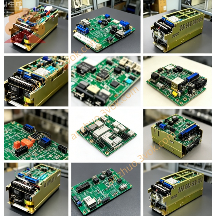
JANCD-JCP05
Description
I. Product Overview
Brand: Yaskawa (Anson)
Model: JANCD-JCP05-1 (abbreviated as JCP05)
Series: YASNAC J300 (J30 upgraded model, high-speed machining type)
Function: Motion control CPU board (not PLC board; PLC board is JCP02B)
Status: Factory discontinued, difficult to replace, dependent on second-hand / repair replacement
Alias: J300 Type C Motion Board, part number DF9202312-C0F
Core purpose:
Multi-axis linkage control for milling machines, machining centers, and turning centers (up to 8 axes)
High-speed high-precision interpolation (straight line / arc / spline), servo axis + spindle synchronization
Communication coordination of management system bus, I/O, PLC and display unit
II. Technical Parameters
Processor: 32-bit high-speed motion CPU, operation cycle ≤ 0.1ms
Control axes: Maximum 8-axis linkage (including servo axes and spindle)
Servo interface: MECHATROLINK-II bus, compatible with Anson Σ series servo
System bus: J300 dedicated backplane bus, data throughput 100MB/s
I/O connector: ×1 (connects PLC board and external I/O)
Power supply: DC24V (backplane power supply, power consumption approximately 35W)
Size / Weight: Approximately 245×210×30mm, weight 2.5kg
Operating environment: Temperature 0–55℃, humidity 30%–85% (no condensation)
Protection mechanism: Overcurrent, overvoltage, overheat, communication abnormal self-diagnosis
Comparison with JCP04:
JCP04: J300 standard motion board, up to 6 axes
JCP05: J300 high-speed version, 8 axes + faster operation, compatible with high-speed machining centers
III. Installation and Wiring
1. Installation (backplane slot in cabinet)
Power off and wait for capacitor discharge (≥ 5 minutes).
Align with the Motion-specific slot of the J300 cabinet (usually Slot 0).
Push in evenly, tighten the upper and lower fixing screws (torque 0.8–1.2N·m).
Confirm the board card indicator lights: PWR on (power normal), RDY flashing (standby).
2. Wiring (3 key interfaces)
CN1 (servo bus): MECHATROLINK-II cable → servo amplifier (Σ-II/Σ-III)
Pins: 1- SG, 2- TX+, 3- TX-, 4- RX+, 5- RX-, 6- 24V
CN2 (system bus): Flat cable → J300 backplane (connects PLC board, I/O board)
CN3 (I/O signal): Terminal block → external emergency stop, limit, reference point switch
Critical signals: EMG (emergency stop, normally closed), LIMIT± (positive/negative limit), REF (reference point)
3. Wiring points
Servo bus cable shield layer single-ended grounding (on the cabinet side), length ≤ 50m.
24V power supply line use 1.5mm² copper wire, avoid in the same slot as power lines.
All connectors locked in place to prevent vibration loosening.
IV. Maintenance and Care
1. Daily maintenance (monthly)
Cleaning: After power off, use dry compressed air (0.4–0.6MPa) to blow dust off the board card, focus on cleaning the heat sink and slots.
Visual inspection: Capacitor no bulging / leakage, solder joints no oxidation, connectors no loosening.
Backup: Execute system parameters and program backup to USB via CNC panel.
2. Regular maintenance (every 6 months) Battery replacement: Replace the SRAM backup battery (CR2032, 3V). Replace within ≤ 5 minutes without power loss to avoid data loss.
Connector tightening: Re-tighten all connection terminals and the fixing screws of the board.
Heat dissipation check: Confirm that the cabinet fan is working properly and the air duct is not blocked.
3. Long-term shutdown (> 3 months)
Before power off, fully back up system data.
Remove the backup battery to prevent leakage and corrosion of the circuit board.
Dry the cabinet to maintain humidity < 60%.
V. Fault Troubleshooting
1. Common fault codes (displayed on CNC panel)
ALM01: Motion board not ready → Check 24V power supply, backplane connection, PWR light status.
ALM02: Servo communication abnormal → Check MECHATROLINK cable, connector, servo power.
ALM03: Overheating → Clean heat sink, check cabinet fan, and whether the environmental temperature exceeds the limit.
ALM04: Axis number exceeds limit → Verify that the set axis number in the parameters is ≤ 8.
ALM05: SRAM data error → Restore backup parameters or replace the battery and reset after reconfiguration.
2. No display / Non-starting
Check the total power supply of the cabinet and 24V output for normal operation.
Unplug the JCP05 board, clean the gold fingers (wipe with absolute alcohol).
Replace the same model board and confirm if the original board is damaged.
3. Motion abnormalities (jitter, inaccurate positioning)
Servo communication: Check the shielded cable of the bus and the connector to eliminate interference.
Parameter matching: Confirm that the servo parameters are consistent with the CNC axis parameters (such as electronic gear ratio).
Mechanical issues: Check if the screw rod, coupling, and guide rail are loose or worn.
4. Troubleshooting principles
First power supply then load, first hardware then software, first external then internal.
Prioritize data backup to avoid data loss during troubleshooting.
VI. Replacement and Procurement
There is no original part replacement. Only used, second-hand / refurbished boards of the same model or repaired old boards can be used.
Procurement points: Verify the model JANCD-JCP05-1, serial number, and ensure there are no signs of repair on the appearance.
Get a Quote