
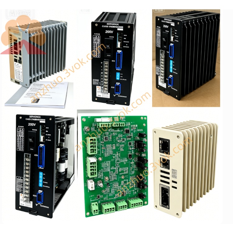
JANCD-JBB12
Description
I. Basic Information
Model: JANCD-JBB12 (The complete model is usually JANCD-JBB12-1)
Brand: YASKAWA (Yaskawa Electric)
Applicable System: YASNAC J300 CNC (Type B control cabinet)
Function: System backplane / Motherboard (Backboard), overall signal and power center
Board Number: J300 Type B Backboard (ACGA version)
Weight: Approximately 2.3 kg (5 lb)
Origin: Japan
II. Core Functions (Compared with JBB03, it is an upgrade / compatible alternative)
Multi-slot Capacity: Provides J300 standard slots, for installing CPU, I/O, axis control, power supply, and communication expansion boards.
Bus Interconnection: Integrated data / address / control bus, enabling high-speed communication and synchronization of each board card.
Power Distribution: Connect external AC, distribute DC5V, ±12V, DC24V to each slot via the backplane; built-in main fuse and branch fuse.
External Interfaces: Front-end leads I/O terminals, servo interface, encoder interface, operation panel interface, handwheel interface.
Version Upgrade: JBB12 is an improved version of JBB03, optimizing bus driver, anti-interference and heat dissipation, and compatible with the entire series of J300 Type B cabinets.
III. Compatible Board Cards (J300 Series)
CPU Board: JANCD-JCP03 / JCP13
I/O Board: JANCD-JIO03 / JIO13
Axis Control Board: JANCD-JAX03 (up to 8 axes)
Power Board: JANCD-JPS03
Expansion Board: JANCD-JEX03 (Communication / Analog Input)
IV. Installation and Wiring Tips (Core of the Manual)
1) Installation
Must be powered off + wear an anti-static wrist strap.
Fix on the rear rail of the J300 control cabinet, screw tightened for vibration prevention.
When inserting the board, the gold fingers face down, align and push in evenly to avoid crooked fingers.
2) Power Wiring (Key)
AC Input: L/N/PE → Backplane power terminals (with JPS03 power board).
DC Output: DC5V (±5%), ±12V, DC24V distributed to each slot.
Fuse: Main fuse 10A/250V; Branch fuses 3A/5A protecting each slot.
3) Signal Interfaces
CN1~CNn: I/O terminal platform (buttons, sensors, solenoids).
SVR1~SVR8: Servo driver bus interface.
ENC1~ENC8: Differential feedback interface for encoders.
OP: Operation panel (buttons, display, handwheel).
V. Common Faults and Troubleshooting
No power for the entire machine: Check AC input, backplane main fuse, JPS03 output.
Board card not recognized: Clean gold fingers, change slots, measure DC5V bus voltage.
I/O signal abnormal: Check CN terminal wiring, 24V power supply, COM common terminal.
Servo alarm: Check SVR/ENC wiring, shield layer grounding, differential signal.
Get a Quote