
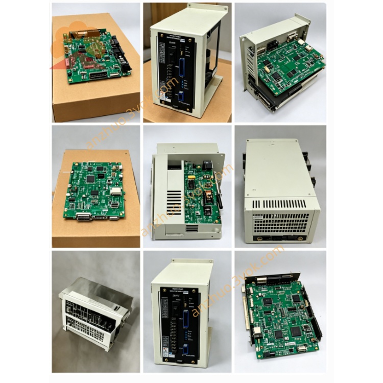
JANCD-I007
Description
I. Product Introduction
1. Usage
It is specifically designed for the control cabinet of the old model Motoman XRC robot, serving as an advanced I/O expansion board.
It integrates safety circuit monitoring + general I/O + external device interface, mainly used in welding, handling, spraying and other process stations.
2. Core Functions
✅ Safety Interlock Processing: Hard logic monitoring of emergency stop, safety door, limit signal
✅ General I/O Expansion: Supplementing the insufficient standard I/O board slots
✅ Peripheral Special Interface: Compatible with welding machines, manipulators, PLC linkage signals
✅ Status Monitoring: On-board LED, real-time display of I/O and safety circuit status
✅ System Bus Communication: High-speed data interaction with XRC main control board
3. Electrical Specifications
Model: JANCD-I007-1 (I007 is omitted - 1)
Input: 32 DC24V (including 8 safety-specific inputs)
Output: 24 DC24V transistors, single point 0.5A
Interfaces: CN1 (50-pin), CN2 (40-pin), CN3 (20-pin)
Power Supply: Backplane DC5V + external DC24V (2A)
Size: Approximately 310×215 mm (standard JANCD large board)
Temperature: 0℃~40℃, no condensation
Humidity: ≤80%, no condensation
II. User Manual (Core Points)
1. Installation (XRC Control Cabinet)
Slot: XRC dedicated I/O slot (ST#03/ST#04)
Fixation: 4 M3 screws, torque 0.8~1.0 N·m
Compatibility: Only XRC models, not applicable to ERC / new DX series cabinets
2. Wiring (CN1/CN2/CN3)
CN1 (50-pin): General input 24 points + output 16 points
CN2 (40-pin): Safety input 8 points + dedicated output 8 points
CN3 (20-pin): Power + communication + status signal
Safety Input: NPN type, low level valid, connect emergency stop / safety door
Output Wiring: Positive pole of load connected to 24V+, negative pole connected to OUTx, common terminal COM connected to 0V
⚠️ Safety circuit must not be paralleled, must be independently wired to ensure reliable shutdown
3. I/O Address (XRC System)
General Input: IN100~IN131
General Output: OUT100~OUT123
Safety Signal: Fixed address of the system, cannot be modified
Check: Teach Pendant → Input/Output → Extended I/O
4. Fault Troubleshooting
Safety Error: Check CN2 wiring, emergency stop button, safety door contacts
I/O No Response: Check DC24V power supply, CN3 communication line, board card pins
Get a Quote