
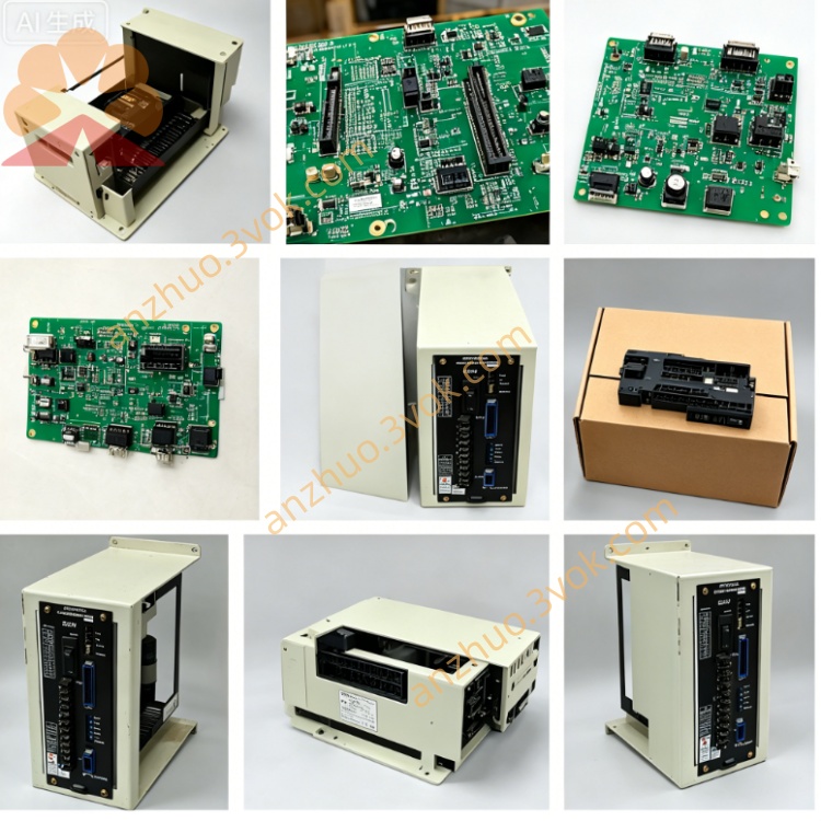
jancd-i004c
Description
I. Product Introduction
1. Function
Used for the control cabinet of Motoman XRC/ERC robots to achieve digital signal interaction between the robot and external devices (PLC, sensors, fixtures, safety doors, emergency stop).
40 DC24V inputs + 40 DC24V outputs are provided. General I/O can be freely assigned addresses.
2. Core Functions
✅ Collect emergency stop, safety door, limit switch, etc. safety interlock signals
✅ Control fixtures, solenoid valves, conveyor belts, etc. actuators
✅ Connect and isolate with upper-level PLC / machine I/O signals
✅ Built-in LED, real-time display of each I/O status for easy diagnosis
✅ Support ladder diagram programming, custom logic
3. Electrical Specifications
Input: 40 points, DC24V, NPN (low level valid)
Output: 40 points, transistors, DC24V, maximum 0.5A / point
Interface: CN1~CN3 (3 50-pin flat cable sockets)
Power supply: Backplane DC5V + external DC24V (recommended independent 24V power supply)
Size: Approximately 310×215 mm (standard JANCD large board)
Weight: Approximately 0.7~0.8 kg
Operating temperature: 0℃~40℃, no condensation
Relative humidity: ≤80%, no condensation
II. User Manual (Key Points)
1. Installation (XRC/ERC Control Cabinet)
Slot: Standard I/O slot (e.g., ST#02)
Fixation: 4 M3 screws, tightening torque 0.8~1.0 N・m
Connection: Gold fingers plug into the control cabinet base plate; CN1~CN3 connect external I/O cables
2. Wiring (CN1~CN3, each port 50 pins)
Input (IN0~IN39):
Common terminal: COM1~COM3 (24V+)
Signal terminal: INx connects to the negative pole of the external switch/sensor (NPN)
Output (OUT0~OUT39):
Common terminal: COM4~COM6 (0V)
Signal terminal: OUTx connects to the negative pole of the load, positive pole connects to 24V+
⚠️ Output must not overload: single path ≤0.5A, entire board ≤1.5A
3. I/O Address Allocation (XRC/ERC System)
General input: IN0~IN39 → Address 00010~00047
General output: OUT0~OUT39 → Address 00050~00087
View / Force: Teaching device → Main menu → Input / Output → General I/O
4. Fault Diagnosis
Input does not light up: Check 24V power supply, COM terminal whether connected to 24V+, sensor polarity
Output does not actuate: Check load wiring, COM terminal whether connected to 0V, program / ladder diagram logic
Communication error: Check board card tightness, cable connection, firmware version matching
Get a Quote