
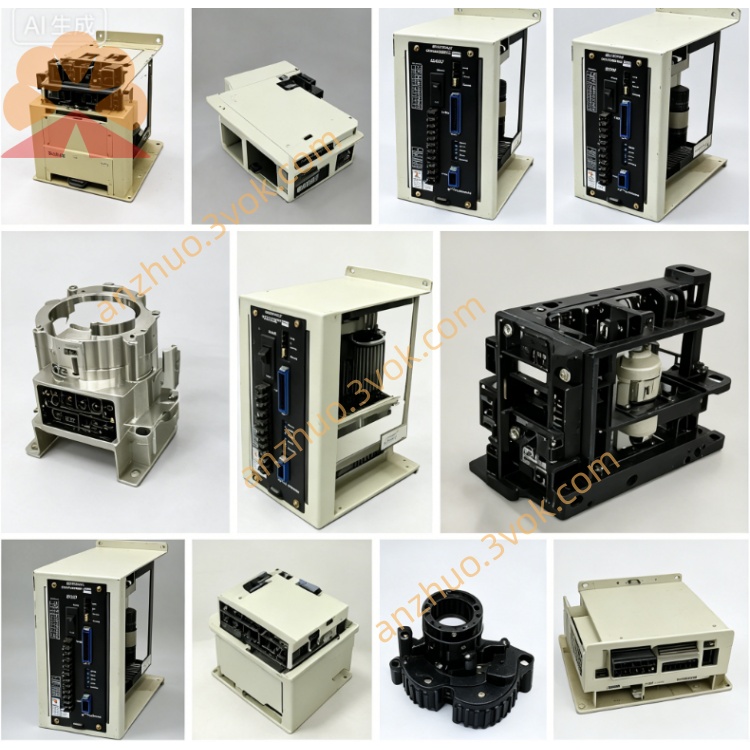
JANCD-I003E
Description
I. Product Introduction
1. Function
Used for the control cabinet of Yaskawa ERC series robots, responsible for the digital signal interaction between the robot and external devices (PLC, fixtures, conveyor belts, sensors, safety doors, emergency stop).
It provides 40 DC24V inputs + 40 DC24V outputs, universal I/O, and can freely assign addresses.
2. Core Functions
✅ Collection of safety signals such as external start/stop, emergency stop, safety door, limit switch, etc.
✅ Control of actuators such as fixture clamping/release, conveyor belt start/stop, solenoid valve, indicator light, etc.
✅ Connection and isolation with the upper-level PLC / machine I/O signals
✅ Built-in LED, real-time display of each I/O status
✅ Support for ladder diagram programming for custom logic
3. Specifications and Parameters
Input: 40 points, DC24V, NPN (low level valid)
Output: 40 points, transistors, DC24V, maximum 0.5A / point
Interface: CN1~CN4 (4 50-pin flat cable sockets)
Power Supply: Backplane DC5V + external DC24V (recommend external independent 24V to avoid interference)
Size: Approximately 310×215 mm (standard JANCD large board)
Weight: Approximately 0.8 kg
Operating Temperature: 0℃~40℃, no condensation
II. User Manual (Core Points)
1. Installation (ERC Control Cabinet)
Installation Slot: ST#02 (standard I/O slot)
Fixation: 4 M3 screws, tightening torque 0.8~1.0 N・m
Connection: CN1~CN4 connect external I/O cables; backplane gold fingers plug into the control cabinet base plate
2. Wiring (CN1~CN4, each port 50 pins)
Input (IN0~IN39):
Common terminal: COM1~COM4 (24V+)
Signal terminal: INx connects to the negative pole of the external switch/sensor (NPN)
Output (OUT0~OUT39):
Common terminal: COM5~COM8 (0V)
Signal terminal: OUTx connects to the negative pole of the load, positive pole connects to 24V+
⚠️ Output must not overload: single path ≤ 0.5A, entire board ≤ 1.5A
3. I/O Address Allocation (ERC System)
General Input: IN0~IN39 → Address 00010~00047
General Output: OUT0~OUT39 → Address 00050~00087
View / Force: Teaching device → Main menu → Input / Output → General I/O
4. Fault Troubleshooting
Input does not light up: Check 24V power supply, whether COM terminals are connected to 24V+, polarity of sensors
Output does not actuate: Check load wiring, whether COM terminals are connected to 0V, whether output is prohibited by program / ladder diagram
Communication error: Check whether board card is plugged tightly, whether cable is loose, whether version is matched (REV A01)
Get a Quote