
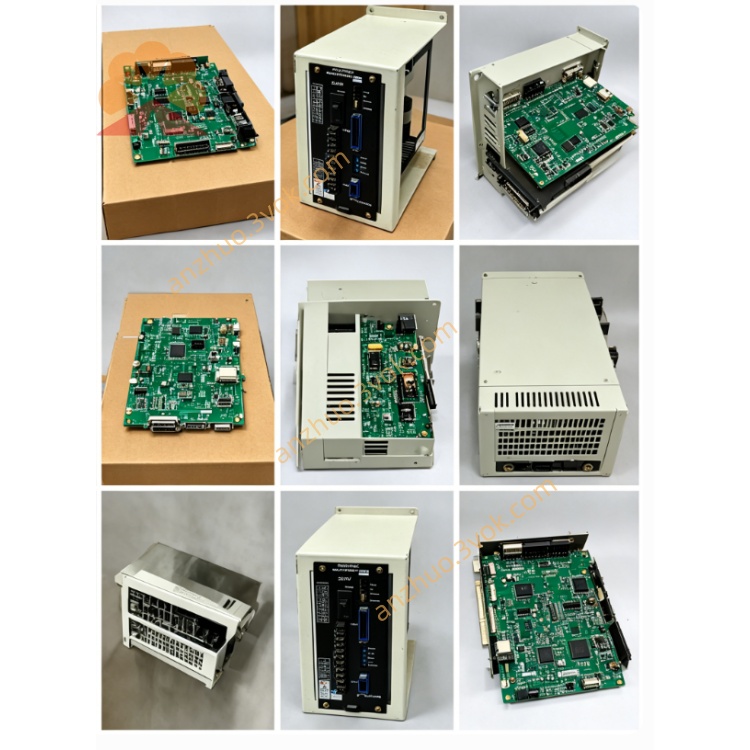
JANCD-GSY01
Description
2. Core Functions
Serial Bus Communication: Responsible for high-speed data interaction between the CNC system and servo units (such as the Σ series), as well as I/O modules, transmitting G codes, position instructions, and status feedback.
Axis Control Expansion: Supports up to 4-axis linkage control, dual-mode compatibility of pulse/bus, and is suitable for the expansion of axis numbers required by Mazak, Ohtsubo, etc. machines.
Signal Conversion:
Servo Enable, Alarm, and Stop Signal Relay;
Encoder Feedback Signal Preprocessing (differential to single-ended conversion, signal amplification);
Emergency Stop and Limit Signal Hardware-level Safety Interlock.
System Diagnosis: On-board fault self-check circuit, power-on self-test (POST), and status output through backplane indicator lights; supports online monitoring of communication bit error rate and axis control synchronization accuracy.
3. Hardware Specifications
3.1 Electrical Parameters
Power Supply: DC5V ±5% (backplane power supply, no external connection required)
Power Consumption: ≤15W
Communication Interfaces:
CN1 (Servo Bus): High-speed differential, maximum 10Mbps, maximum 50m;
CN2 (Encoder): A/B/Z phase signals, 5V differential, supports absolute/incremental encoders;
CN3 (I/O): 24V NPN/PNP compatible, input 8 points / output 4 points;
CN4 (Backplane): JANCD-GSR01 dedicated slot, gold finger connection.
3.2 Environmental Parameters
Operating Temperature: 0℃ ~ +55℃
Storage Temperature: -25℃ ~ +85℃
Relative Humidity: ≤90% (no condensation)
Vibration: 0.5g (10~150Hz)
Protection Grade: IP20 (installed in the cabinet)
4. Slots and Wiring
4.1 Backplane Slots (JANCD-GSR01)
Slot1: GMMxx (CPU Board)
Slot2: GMRxx (Display/Graphic Board)
Slot3: GSY01 (This Board, Communication/Axis Control)
Slot4: GSCxx (Logic Control Board)
Slot5: GSP10 (Panel I/O Board)
4.2 Interface Definitions (CN1~CN4)
CN1 (Servo Bus, 15-pin D-Sub) Table
Pin Signal Explanation
1 TX+ Transmit +
2 TX- Transmit -
3 RX+ Receive +
4 RX- Receive -
5 GND Ground
6-15 NC Empty
CN2 (Encoder, 20-pin)
A+, A-, B+, B-, Z+, Z-: Differential signals of the encoder
+5V, GND: Power supply for the encoder
PE: Shield ground
CN3 (I/O, 12-pin)
IN1- IN8: 24V input (NPN/PNP)
OUT1- OUT4: 24V/0.5A output (transistor)
6. Installation and Replacement
Power-off operation: Turn off the total power of CNC, wait for the capacitor to discharge (≥5 minutes).
Slot alignment: Align the GSR01 backplane Slot3, insert uniformly with force, ensure the gold fingers are fully in contact.
Fixing screws: Tighten the 2 M3 fixing screws on the board card (torque 0.8-1.0N・m).
Connection: Connect the servo, encoder, and I/O cables according to CN1-CN3 definitions, single-ended ground of the shield layer (on the cabinet side).
Power-on self-check: After powering on, the **PWR (green)** light is always on, **RUN (yellow)** flashes (1Hz) indicating normal; **ERR (red)** is always on indicating a fault.
6. Fault Diagnosis and Troubleshooting
6.1 Indicator Light Status
PWR (green): Always on = Normal power supply; Off = Backplane power supply failure or board card short circuit.
RUN (yellow): Flashing (1Hz) = Normal operation; Always on = Initialization failure; Off = Not started.
ERR (red): Flashing = Communication error; Always on = Hardware failure / Axis control abnormal.
6.2 Common Faults
Communication interruption (ERR flashing)
Troubleshooting: CN1 cable damage, poor shielding grounding, servo address conflict;
Treatment: Replace the shielding wire, re-ground, check the servo address.
Axis control alarm (ERR always on)
Troubleshooting: Encoder wiring error, abnormal power supply voltage, board card chip damage;
Treatment: Check CN2 wiring, measure DC5V, replace the board card.
I/O no response
Troubleshooting: CN3 wiring error, 24V power missing, output transistor burned out;
Treatment: Check I/O definition, check the external 24V, replace the board card.
7. Maintenance and Care
Regular inspection: Every 3 months, power off, wipe the gold fingers with isopropyl alcohol, check the screws for tightness, and check the aging of the cables.
Dust prevention: Keep the cabinet clean, avoid dust accumulation (suggestion to equip a dust cover).
Anti-static: Wear an anti-static wristband during operation to avoid static breakdown of the chips.
8. Precautions
Prohibit hot plugging: Must power off before inserting or removing the board card; otherwise, burn the chip.
Prohibit overloading: The output end of CN3 must not be connected to inductive loads (such as relays), a rectifier diode must be added.
Prohibit modification: Unauthorized modification of the circuit, replacement of components will result in the invalidation of the warranty and may cause system crash.
Get a Quote