
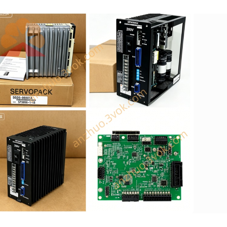
JANCD-GSC
Description
I. Basic Information
Model: JANCD-GSC01 / GSC01B / GSC02 (Commonly three types)
Brand: Yaskawa (Yaskawa)
Origin: Japan
Type: Built-in PLC / Sequence Control PCB (Sequence Control PCB)
Compatible System: YASNAC 2000G / 3000G CNC (PLC core for machine side)
Main Control: GMM11/GMM12/GMM22 (Must be paired with GMM)
Board Form: Full-length industrial board, Slot 4 slot position (GMM = Slot 1, GMR/GRT = Slot 2, GRS = Slot 3)
Original Part Number:
GSC01: DF7000066
GSC02: DE6428681
Status: Discontinued (OUT OF STOCK), only second-hand / refurbished items are available for circulation
II. Core Functions (Differentiating GMR/GRS/GRT)
✅ Built-in PLC operation: Executes machine tool ladder diagram programs (M/S/T codes, interlocks, safety circuits)
✅ I/O logic transfer: 16 input / 16 output signals from GRS01 are processed by GSC logic and then transmitted to GMM
✅ Panel signal analysis: Logic operations of operation panel / MDI keys, mode switching (automatic / manual / MDI)
✅ Alarm and diagnosis: PLC-side alarms (such as emergency stop, limit stop, door opening) generated and displayed
✅ Spindle / Cooling control: Spindle start/stop, speed ratio, cooling pump / lubrication pump logic
❌ No graphics / display: Not responsible for CRT/VGA display (GMR/GRT is responsible)
❌ No motion control: No interpolation, no servo drive (GMM + servo unit is responsible)
III. Hardware Specifications (GSC01/GSC02)
Power supply: Backplane DC5V, approximately 12W
CPU: GSC01 = 16-bit; GSC02 = 32-bit (faster operation)
Program memory: GSC01 = 64KB; GSC02 = 128KB (ladder diagram capacity)
Scan cycle: GSC01 ≈ 8ms; GSC02≈2ms
Temperature: Working range 0℃ to +55℃; Storage range **−25℃ to +85℃**
Weight: Approximately 0.8kg
IV. Interface Definitions (CN1 to CN3)
CN1: System bus → Connects to GMM main controller (data + power supply)
CN2: I/O bus → Connects to GRS01 (16 input / 16 output signals)
CN3: Panel bus → Connects to GRT01 (CRT panel) or directly operates the panel Indicator light
PWR: Normal power supply (always on)
RUN: PLC is running (1Hz flashing)
ALM: PLC is alarmed (always on, such as ladder diagram errors, I/O failures)
VII. Model Differences (GSC01 vs GSC01B vs GSC02)
GSC01 (Basic Version): 16-bit CPU, 64KB, 8ms scanning, compatible with GMM11 (4 axes)
GSC01B (Improved Version): Same as GSC01, optimized for anti-interference, compatible with GMM11/GMM12
GSC02 (High Performance Version): 32-bit CPU, 128KB, 2ms scanning, compatible with GMM22 (8 axes)
VI. Pairing Rules (Strict)
✅ GMM11 + GMR22 + GRS01 + GSC01B: 2000G standard configuration
✅ GMM12 + GMR22 + GRS01 + GSC01B: 3000G basic configuration
✅ GMM22 + GMR24 + GRS01 + GSC02: 3000G high-end configuration (8 axes + 3D)
❌ Mix GSC with GRT: Slot2 can only be inserted with GMR or GRT, GSC is fixed in Slot4
VII. Core Differences from GMM/GMR/GRS/GRT
GMM: Main control / motion control, Slot1, core board
GMR22/24: Graphic display, Slot2, VGA/3D
GRT01: CRT display + panel, Slot2, old-fashioned CRT
GRS01: I/O + communication, Slot3, 16 inputs / 16 outputs + RS232
GSC01/02: PLC / sequence control, Slot4, ladder diagram / logic
VIII. Common Faults
PLC does not run: PWR does not light up (backplane 5V abnormal), RUN does not flash (CN1 loose, ladder diagram damaged)
Panel has no response: CN3 contact failure, mismatch between GSC and GRT versions
Frequent ALM: Ladder diagram logic error, external I/O short circuit, GSC aging
Program loss: Backup battery failure (board-level lithium battery, life approximately 5 years)
Get a Quote