
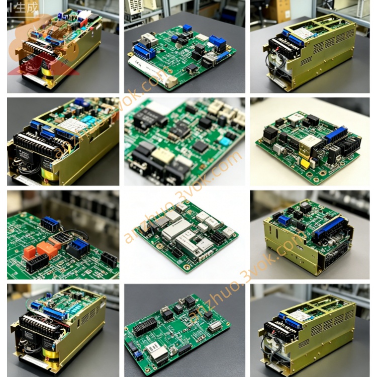
JANCD-GMM12
Description
I. Basic Specifications
Model: JANCD-GMM12
Type: 32-bit main CPU + program/data memory composite board
Compatible systems: YASNAC 2000G (general type), 3000G (standard/high-end compatible)
Power supply: DC5V (direct supply from the back panel, power consumption approximately 30W)
Form: Full-length industrial board card, gold finger slots (Slot1 main slot)
Temperature: Working 0℃~+55℃; Storage -25℃~+85℃
Humidity: 30%~95% RH (no condensation)
Memory: Program storage 512KB, data / tool compensation storage 128KB
Maximum number of linked axes: 6 axes linkage
II. Interfaces and Indicators
CN1: System bus (connects GMR22/GMR24 graphics board, GRT01 display IO board)
CN2: Axis control bus (connects servo amplifier/axis card, 6 axes)
CN3: MDI / panel interface (key scanning, data display interaction)
CN4: RS-232C serial port (DNC program transmission, 1200–9600bps)
Indicators:
PWR: Power normal (always on)
RUN: System running (1Hz flashing)
ALM: System alarm (always on / fast flashing)
MEM: Memory read/write (flashing)
III. Core Functions
Program execution: G/M/T code parsing, straight / circular interpolation, 6-axis linkage trajectory planning (supports complex cavity processing)
Memory management: 512KB part program storage, 128KB parameters / tool compensation / macro program storage (supports larger program capacity)
Display control: Sends coordinate, program, alarm and other display data to GMR22/GMR24, supports high-resolution graphical interface
IO scheduling: Interacts with GRT01, processes machine emergency stop, limit, relay output and other switch quantities, response speed improvement
Communication: RS-232C DNC transmission, external device data interaction, system diagnosis monitoring, supports online debugging
IV. Differences from GMM11/GMM22
GMM11: Basic model, 256KB memory, 4-axis linkage, compatible with 2000G standard type
GMM12: Mid-range model, 512KB memory, 6-axis linkage, compatible with 2000G/3000G general type (mainstream)
GMM22: High-end model, 1MB memory, 8-axis linkage, enhanced computing / anti-interference, compatible with 3000G high-end
V. Installation and Maintenance
Installation: Back panel Slot1 (main slot) of the control cabinet, push vertically and lock, align the gold fingers
Wiring: Back panel DC5V power supply; CN1–CN4 away from power lines / frequency converter, avoid electromagnetic interference
Maintenance: Regular dust cleaning, clean gold fingers; Back up parameters / programs every 6 months (built-in CR2032 battery to maintain data)
Faults:
No display: GMM12 not started, CN1 bus loose, power supply abnormal
Program loss: Memory battery failure (replace with CR2032)
Axis not moving: CN2 axis control bus failure, servo communication abnormal
High alarm frequency: Chip aging, cache error, incompatible with GMR/GRT version
Get a Quote