
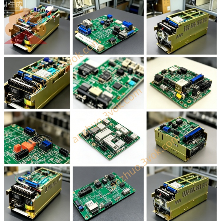
JANCD-G1O02
Description
Technical Specifications
The power supply is obtained through the backplane bus of the chassis. The working voltage is DC24V, and the voltage fluctuation range is kept within a reasonable range. The overall power consumption is stable. A dedicated graphics processing chip is installed, which can drive the operation of conventional display devices. An exclusive storage area is equipped to store interface programs and picture cache data. The board integrates display ports, operation panel ports, hand-wound pulse interfaces, and the system communication bus. The operating temperature range is wide, the storage can tolerate a large temperature span, the working environment is kept dry without condensation, and it has the anti-vibration protection capability for industrial scenarios. The overall specifications are compatible with the standard chassis slot installation.
Installation and Wiring
The board is vertically inserted into the card slot inside the control cabinet. A ventilation and heat dissipation space is reserved around it. Fastening and fixing accessories are used to avoid contact offset caused by vibration. The metal casing of the board is closely connected to the grounding part of the chassis to weaken electromagnetic signal interference. The power transmission and data exchange within the board are completed through the backplane bus. The external connections only include the low-voltage lines for display devices, operation panels, and hand-wound units. According to the board markings, the lines are connected correspondingly. Long-distance signal lines are shielded and grounded in a standardized manner. The strong and weak electrical lines are arranged separately to maintain a safe distance and reduce line interference.
Maintenance and Care
Daily checks include observing the appearance condition of the board surface and the working status of the indicator lights. Check for any damaged or overheated abnormalities in the components. Regularly use a low-pressure dry gas source to clean the board surface and slot dust to ensure the smoothness of the heat dissipation channels. Regularly check the firmness of the connection parts of the lines, check for any aging or leakage problems in the capacitor solder joints, and verify the stability of the grounding connection. When the equipment is left idle for a long time, cut off the power supply, take dust-proof and moisture-proof protection measures, and perform a no-load power-on test run before reactivation to confirm the normal status before putting it back into use.
Troubleshooting
The power indicator light fails to light up, mostly due to abnormal power supply from the bus, damage to the board card fuse components or power supply chips. Check the power supply line voltage, replace the components to determine the fault location. The screen of the equipment is black and unable to display images, mostly caused by loose interface contact, failure of the driving components, or abnormal front-end power supply. Reconnect the lines to detect the signal status. If there is a distorted and blurry screen phenomenon, it is usually due to abnormal cache module, communication interference, or program data abnormalities. Strengthen the connection points and optimize the grounding environment. Check the status of the connection ports and signal acquisition components of the operation panel. If the operation panel buttons cannot trigger instructions, check the status of the connection ports and signal acquisition components. If the equipment runs abnormally and freezes, it is mostly affected by electromagnetic interference or line short-circuit. Regularize the wiring structure, replace the board card of the same specification for testing and operation. The same model board card can be directly replaced and assembled, and after installation, perform a no-load test run to verify the stability of the operation.
Fault Diagnosis
The power indicator light fails to light up, mostly due to abnormal power supply from the bus, damage to the board card fuse components or power supply chips. Check the power supply line voltage, replace the components to determine the fault location. The screen of the equipment is black and unable to display images, mostly caused by loose interface contact, failure of the driving components, or abnormal front-end power supply. Reconnect the lines to detect the signal status. If there is a distorted and blurry screen phenomenon, it is usually due to abnormal cache module, communication interference, or program data abnormalities. Strengthen the connection points and optimize the grounding environment. Check the status of the connection ports and signal acquisition components of the operation panel. If the operation panel buttons cannot trigger instructions, check the status of the connection ports and signal acquisition components. If the equipment runs abnormally and freezes, it is mostly affected by electromagnetic interference or line short-circuit. Regularize the wiring structure, replace the board card of the same specification for testing and operation. The same model board card can be directly replaced and assembled, and after installation, perform a no-load test run to verify the stability of the operation.
Get a Quote