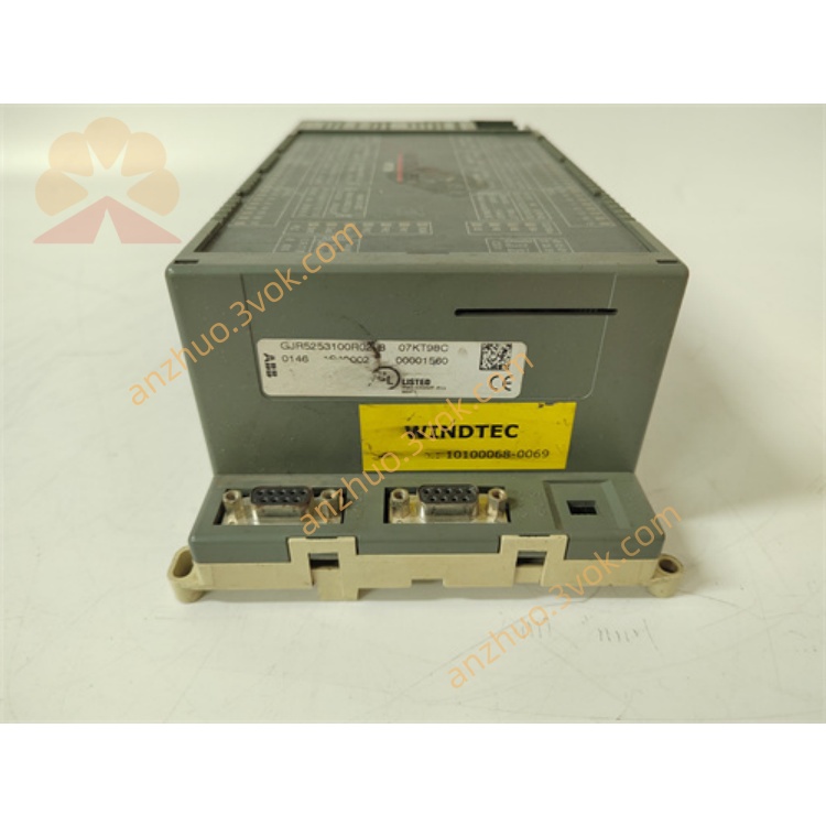
ABB 07KT98C GJR5253100R028 Advant Controller CPU Module
Description
# 1. Quick Overview of Core Parameters
Model: 07KT98C; Part No.: GJR5253100R028
Series: ABB AC31 (Advant Controller 31)
Power Supply: 24V DC ±20% (18–32V DC), approx. 5W
Program/Data Memory: 2MB / 1MB + 256KB Retentive Memory
Integrated I/O
AI: 8 channels, 12bit (±10V/0–10V/4–20mA/PT100)
AO: 4 channels, 12bit (±10V/0–20mA)
DI: 8 channels, 24V DC
DO: 2 channels, 24V DC/0.5A (Transistor Type)
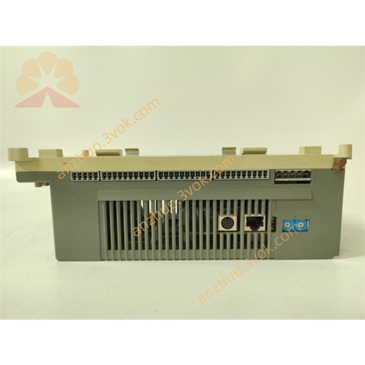
Communication
Ethernet: 10/100Mbps, Modbus TCP (Default IP: 192.168.0.1)
CANopen: Master Station, Default 125kbps
CS31: System Bus
RS232/RS485: Programming / Modbus RTU
Environment: Operating 0~+55℃; Storage -40~+85℃; Humidity 5%–95% RH (Non-condensing)
Installation: Standard 35mm DIN Rail; Dimensions 120×80×65mm; Weight approx. 500g
II. Simplified Operating Instructions
1. Installation
Fix it on the DIN rail, leaving a minimum of 50mm of space for heat dissipation on all sides, and keep it away from heat sources / strong vibrations.
Electrostatic protection: Use an anti-static wrist strap when operating.
2. Wiring (Power-off operation)
Power supply: L+ → 24V+; M → 0V; PE → cabinet ground (≤ 4Ω).
AI/AO: Shielded twisted pair, single-ended grounding; current signal series 250Ω resistor.
DO: Do not directly drive contactors; inductive loads should be connected with a shunt diode.
Communication: Use shielded cables for Ethernet/CANopen/RS485; CANopen: Connect 120Ω terminal resistor at both ends.
3. Power On and Indicator Lights
PWR (green): Always on = Normal; Blinking = Voltage abnormality.
RUN (green): Always on = Running; Blinking = No program / Stopped.
ERR (red): Off = Normal; Blinking = Minor fault; Always on = Serious fault.
4. Software and Programming
Software: Control Builder (IEC 61131-3: LD/FBD/ST).
Configuration: I/O type / range, communication parameters (IP / baud rate / address).
Download: Download after successful compilation; Do not disconnect the communication port while running.
5. Key Precautions
Do not plug or unplug terminals / communication ports while powered on.
Do not exceed AI range, overload DO (≤ 0.5A) or short circuit.
Regularly back up programs / parameters; Tighten terminals and clean heat sinks monthly.
Get a Quote