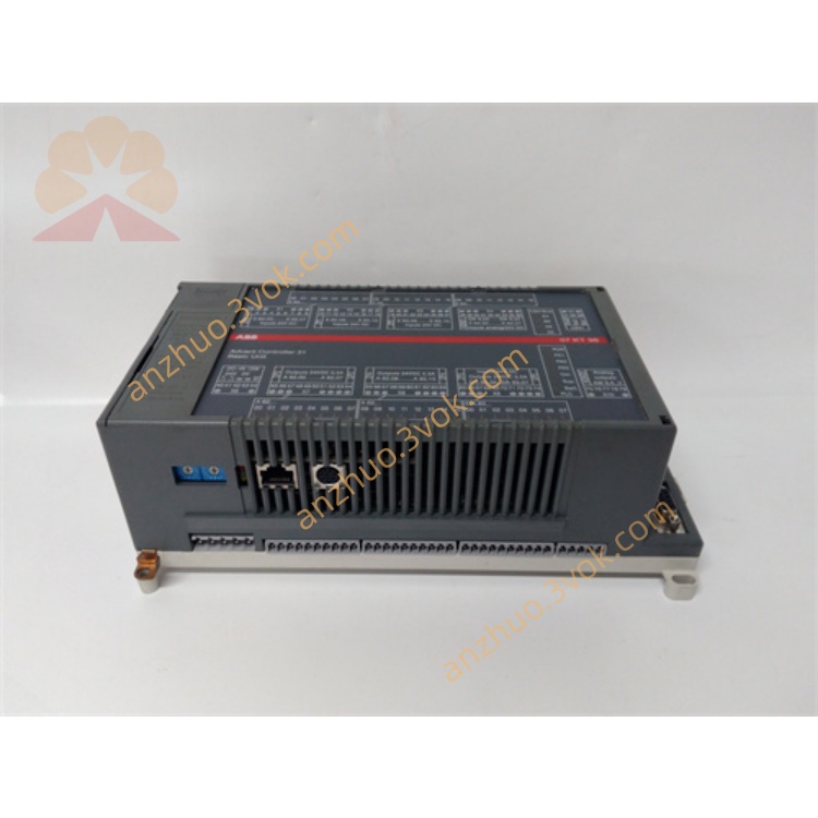
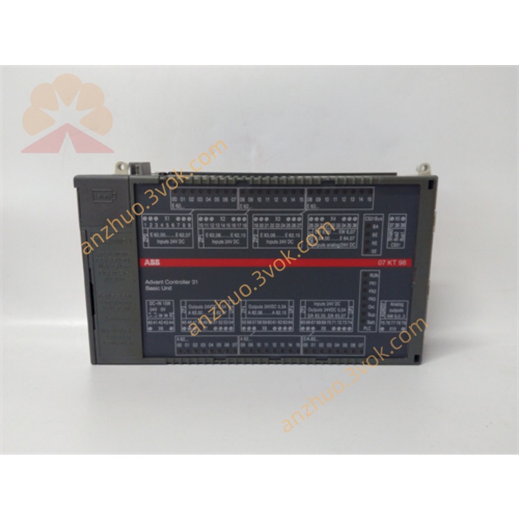
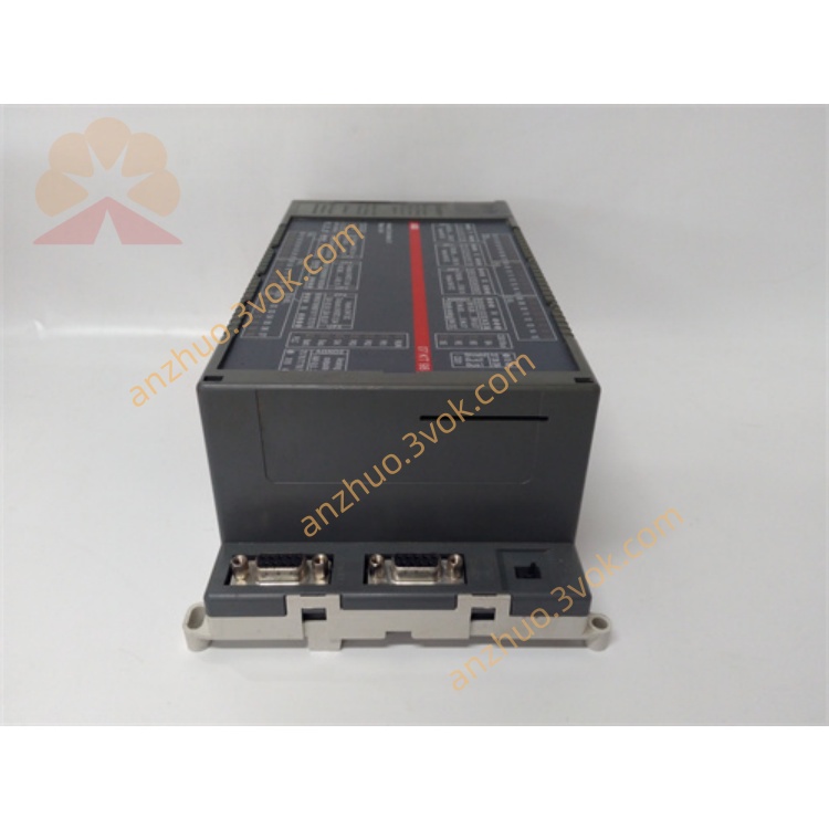
ABB 7KT98 GJR5253100R4278 AC31 H2 PLC CPU Module
Description
Complete User Manual for 7KT98 (GJR5253100R4278) (AC31 H2 Controller)
1. Product Overview
Model: 07KT98 H2
Material No.: GJR5253100R4278 (Replaces R0278/R0270)
Series: ABB AC31 (Advant Controller 31)
Type: All-in-one PLC/CPU (Integrated I/O + Multiple Communication Ports)
Processor: 32-bit; Program Memory: 1 MB; Data Memory: 1 MB + 256 KB Retentive Area
Applications: Water Treatment, HVAC, Packaging Machinery, Small Production Lines, Building Automation, General Process Control
2. Technical Specifications (Complete)
2.1 Power Supply
Voltage: 24 V DC ±20% (18 - 32 V DC)
Power consumption: Approximately 4.8 W
Reverse connection protection: Yes; It is recommended to add a 1A fuse + surge protector
2.2 Integrated I/O (Built-in)
Analog input AI: 8 channels, 12 bits
Voltage: ±10 V / 0~10 V / ±5 V / 0~5 V
Current: 4 - 20 mA (default) / 0 - 20 mA
Temperature: PT100 (2-wire / 3-wire)
Analog output AO: 4 channels, 11-12 bits
Voltage: ±10 V
Current: 0 - 20 mA
Load: Current ≤ 500 Ω; Voltage ≥ 1 kΩ
Digital input DI: 8 channels, 24 V DC (NPN/PNP compatible)
Digital output DO: 2 channels, transistor 24 V DC / 0.5 A (without relay)
2.3 Communication Interface (All Isolated)
Ethernet: RJ45, 10/100 Mbps, Modbus TCP
CANopen: DB9 / Terminal, Master Station, Default 125 kbps
CS31: System Bus (Expansion AC31 I/O Rack)
RS232/RS485: COM1/COM2, Programming, Modbus RTU, Free Protocol
2.4 Environment and Machinery
Operating temperature: 0 ℃ ~ +55 ℃
Storage temperature: -40 ℃ to +85 ℃
Humidity: 5% - 95% RH (no condensation)
Dimensions (width × height × depth): Approximately 120 × 80 × 65 mm
Weight: Approximately 500 grams
Installation: Standard DIN 35 mm rail
3. Unboxing and Storage
Opening and inspecting the box: Model 07KT98, material number GJR5253100R4278, no damage to the appearance, no deformation of the terminals, all accessories are complete (rail clips, manual, certificate of conformity).
Electrostatic protection: Wear anti-static wristbands throughout the process to prevent damage caused by static electricity.
Long-term storage: In a dry, dust-free, and non-corrosive gas environment, at -25 ℃ to +75 ℃; Sealed with desiccant and kept dry, for no more than 6 months.
4. Mechanical Installation (DIN Rails)
Guide rail: Standard 35 mm DIN guide rail, horizontal, stable, and without deformation.
Installation:
Align the bottom snap of the controller with the guide rail and insert it from top to bottom. You will hear a "click" sound.
Push the clips on both sides tightly. The vibration environment must be locked in place.
Spacing: Leave a minimum of 50 mm of space on all sides for heat dissipation. Do not stack.
Environmental Prohibition: Keep away from heat sources (frequency converters, transformers), strong vibrations (>0.1g), metal dust, and conductive fibers.
5. Electrical wiring (must be operated with power off)
5.1 Power Connection (24 V DC)
Terminal definition:
L+: 24 V DC positive pole
M: 0 V (Negative pole)
PE: Protection Ground (must be connected to the cabinet ground; grounding resistance ≤ 4 Ω)
Connection Points:
Wire diameter: 0.75 - 1.5 mm², cold-pressed terminal.
Power supply end: 1 A fuse + 24 V surge protector.
Cabling: Power supply and I/O/communication lines are separated in different slots, with a spacing of ≥ 10 cm; keep away from 220/380 V.
5.2 Analog Input AI (8 channels)
Voltage signal: Signal + → AIx; Signal - → COM
Current signal: Signal + → AIx; Signal - → COM; Series 250 Ω resistor (converts to 1-5 V)
PT100 (3-wire recommended): AIx, COM, compensation terminal; 2-wire: Connect the compensation terminal to COM and short it.
Cable: Shielded twisted pair, with the shielding layer grounded at one end (on the cabinet side), and grounding at both ends is prohibited.
5.3 Analog Output AO (4 channels)
Voltage / Current: Load + → AOx; Load - → COM
Prohibition: Prohibit direct short circuit of AO; Add a rectifier diode for inductive loads.
5.4 Digital Inputs/Outputs
DI: 24 V DC, COM (common) terminal, input current ≥ 10 mA.
DO: 24 V DC / 0.5 A. Do not directly drive the contactor (use an intermediate relay instead); for inductive loads, add a rectifier diode.
5.5 Communication Wiring
Ethernet: Standard shielded network cable, RJ45, single-ended grounding.
CANopen: CAN_H, CAN_L, GND; The start and end nodes are connected to 120 Ω termination resistors and are grounded at one end.
RS485: A/B/GND; Terminal 120 Ω, common ground.
6. Power-on and Indicator Light Status
6.1 Pre-power-on Inspection (Required)
Mechanical: Firm, sufficient cooling space, no foreign objects.
Electrical: There is no short circuit in the power supply, PE is reliably grounded, I/O/communication wiring is correct, and the shielding grounding is in compliance.
Environment: No condensation, normal temperature and humidity.
6.2 Indicator Lights (Front)
PWR (green): Constantly on = Normal; Blinking = Under-voltage / Over-voltage / Short circuit.
RUN (Green): Constantly on = Running; Blinking = Stopped / No program / Standby.
ERR (Red): Off = Normal; Blinking = Minor Fault; Always On = Severe Fault (short circuit, program crash, hardware damage).
6.3 Initial Power On
Only 24 V DC: RUN flashes, ERR goes out (empty program).
Connecting to the programming software Control Builder:
Programming interface: RS232/USB - RS232 or Ethernet.
Default parameters: Baud rate 9600, Address 1; IP: 192.168.0.1.
Download empty program / default configuration → RUN remains constantly on, initialization completed.
7. Software Configuration and Programming (Control Builder)
7.1 I/O Configuration
AI: Select type (voltage / current / PT100), range, filtering (default 100 ms), fault threshold.
AO: Type, range, upper and lower limits, fail-safe value.
DI/DO: Address, Polarity, Rising / Falling Edge.
7.2 Communication Configuration
Ethernet: IP, subnet mask, gateway; Modbus TCP master/slave stations.
CANopen: Baud rate, node address, PDO/SDO mapping.
RS485: Baud rate, data bits, parity bit, address; Modbus RTU.
7.3 Programming
Language: IEC 61131-3 (LD/FBD/ST/IL)
Program structure: Main loop, interrupt, subroutine, function block.
Download: After successful compilation, download to the controller; during operation, do not disconnect the communication / program port.
8. Operation and Maintenance
8.1 Daily Operation Prohibitions
Do not plug or unplug the terminals / communication ports / programming ports while powered on.
It is prohibited to make any wiring changes during operation (please stop the machine and cut off the power first).
Prohibit AI from exceeding the range (such as ±10 V input 15 V).
Prohibit overload (≤ 0.5 A) or short circuit of DO.
It is prohibited to operate without shielding in an environment with strong interference (such as from frequency converters and electric welding machines).
8.2 Regular Maintenance
Monthly: Check the indicator lights, terminals (tighten to 0.5 - 0.8 N·m), cooling (dry compressed air blowing, ≤ 0.5 MPa), and cable aging.
Quarterly: Program/parameter backup (local + cloud), AI/AO calibration, communication quality test.
Each year: Comprehensive cleaning, insulation test, re-measurement of grounding resistance, firmware upgrade (if applicable).
9. Fault Diagnosis (Common)
ERR constantly lit: I/O short circuit, power abnormality, program error, hardware damage → Power off and check the wiring / load, restore factory default settings and re-run the program.
RUN indicator not lit: No program, program damaged, hardware failure → Re-download the program. If it cannot be restored, replace the controller.
AI without signal / glitch: Wiring error, double-ended grounding with shielding, interference, sensor failure → Check wiring, single-ended grounding, stay away from interference source.
Communication failure: Network cable / bus damaged, terminal resistor incorrect, IP / address conflict, baud rate mismatch → Check the cables, terminal resistors, and parameters.
Get a Quote