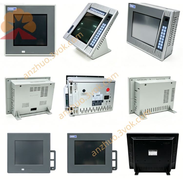
XYCOM XVME-531 Product Description
Description
XYCOM XVME-531 Product Description
I. Product Overview
The XVME-531 is a 6U dual-high VMEbus 16-channel analog output module launched by XYCOM (now under Pro-face/Acromag). It is available in two versions: /1 non-isolated and /2 high-isolated. It is designed for industrial multi-channel, high-precision analog control scenarios based on the VME architecture. Its core positioning is a high-density, isolated, multi-range, industrial-grade analog output card. Each slot integrates 16 independent outputs, suitable for process control, servo drives, test measurement, power monitoring, and high-density analog output expansion for outdated VME systems. This module has been officially discontinued and is mainly available in second-hand, refurbished, and inventory spare parts in the market.
Core Positioning
As a VMEbus standard slave device, XVME-531 focuses on "6U dual high + 16 channels high density + 12-bit high precision + voltage/current dual mode + optional 500V isolation + independent calibration + wide temperature reliability". Each slot can achieve 16-channel analog output. The /2 version provides 500V optical isolation per channel (digital and analog circuits isolated), providing strong anti-interference. It solves the core pain points of multi-channel, strong interference, and long-distance analog signal output in industrial sites.
II. Core Functional Characteristics
1. Standard VMEbus interface (fully compatible slave device)
Fully complies with IEEE 1014 VMEbus specification, compatible with all 6U VME chassis and backplanes, operates in standard slave device mode, supports A16 short address space, base address configured via jumper, fixedly occupying 1KB address boundary, avoiding system address conflicts. Data width compatible with D08/D16, compatible with 8/16-bit VME master controllers, backplane connection uses P1/P2 connectors, supports VME standard interrupts (I1-I7) and system fault signals (SYSFAIL), plug-and-play.
2. 16-channel independent analog output (core function)
Equipped with 16 independent 12-bit D/A converters, providing 16 independent, hardware-configurable analog output channels (channels 0-15), in two versions:
XVME-531/1: Non-isolated version, suitable for low-interference, short-distance control scenarios;
XVME-531/2: Isolated version, each channel 500V optical isolation (digital and analog circuits isolated), highly resistant to interference.
Each channel can be independently set to voltage or current mode, channels do not interfere with each other, can be connected to control valves, frequency converters, servo amplifiers, industrial instruments, etc.
Resolution: 12-bit D/A converter, total error ≤ ±0.5 LSB (voltage), ±0.66 LSB (current), linearity ±0.5 LSB.
Voltage range (single / bipolar): 0-5V, 0-10V, ±5V, ±10V, covering industrial standard voltage range.
Current range (/2 version): 4-20mA (industrial standard current loop), suitable for long-distance transmission.
Drive capability: maximum voltage output drive current ±10mA; maximum load resistance for current output 500Ω.
Response speed: conversion time 42μs; voltage stability time 8μs, current stability time 30μs, dynamic response fast.
Calibration function: each channel independent gain / bias adjustable, onboard calibration circuit, long-term stability good.
3. Flexible control and status monitoring
Supports independent update of single channel and synchronous update of multiple channels, compatible with different system real-time requirements; front panel equipped with 50-pin connector and status indicator light, can intuitively monitor module power supply, operation and output status, facilitating rapid troubleshooting in the field.
4. Industrial-grade high reliability design
Standard operating temperature 0℃~+65℃ (wide temperature version - 40℃~+70℃), compatible with industrial harsh environments; circuit board uses multi-layer board wiring, gold-plated gold fingers design, key circuits add filtering and surge protection, strong anti-static and vibration resistance; /2 version has built-in isolated power supply, analog and digital circuits completely isolated, further reducing interference.
III. Hardware Specifications Details
Bus Interface Specifications
Bus Protocol: IEEE 1014 VMEbus, standard slave device mode;
Address Space: A16 short address, jumper configured 1KB boundary base address;
Data Width: D08/D16;
Interrupt Support: VME standard interrupts I1-I7, configurable vector;
Backplane interface: P1/P2 connectors;
Dimensions: 6U (160mm × 233.4mm), single slot;
Weight: approximately 0.5kg.
Analog output specifications
Channel quantity: 16 independent analog outputs;
Converter: 12-bit D/A (per channel independently);
Voltage range: 0–5V, 0–10V, ±5V, ±10V;
Current range (version 2): 4–20mA;
Drive capability: voltage ±10mA, current maximum 500Ω load;
Isolation level (version 2): per channel 500V optocoupler isolation;
Accuracy: voltage ±0.5 LSB, current ±0.66 LSB;
Stabilization time: voltage 8μs, current 30μs;
Calibration: each channel independent gain / bias adjustable.
Electrical and environmental specifications
Power supply: +5V DC (VME bus power supply), typical power consumption 2.8A (full load);
Operating temperature: 0℃–+65℃ (standard), -40℃–+70℃ (wide temperature);
Storage temperature: -40℃–+85℃;
Humidity: 5%–95% RH (non-condensing);
Anti-vibration: meets industrial standards, compatible with equipment vibration environment.
Four. Typical application scenarios
1. High-density actuator driver for industrial process control
Suitable for multi-loop control scenarios in industries such as chemical, energy, and water treatment, 16-channel output for control valves, proportional valves, frequency converters, etc., version 2 with 500V isolation to block ground loop interference, 4–20mA current output suitable for long-distance transmission, ensuring stable multi-channel control.
2. Servo and motion control multi-axis signal output
Used in industrial automation production lines, robot control, output ±10V analog signal to drive multi-axis servo amplifiers, 30μs current stabilization time meets dynamic motion control requirements, 16-channel independent output suitable for multi-axis linkage control.
3. Test measurement and instrument calibration system
Used in industrial test equipment, calibration systems, simulate standard voltage / current signals (such as 4–20mA, 0–10V) to calibrate instruments, test control system response, 16-channel independent output can simultaneously calibrate multiple devices, improving test efficiency.
4. Power and energy monitoring system
Used in substations, power grid monitoring scenarios, output analog signals to control excitation regulators, reactive power compensation devices, version 2 with high isolation design to resist high-voltage side interference, ensuring safe and stable operation of power equipment.
5. High-density output upgrade of old VME systems
Directly replace the low-channel-count analog output modules in old systems, no need to modify the chassis structure, upgraded to 16-channel output (version 2 with 500V isolation), compatible with old VME equipment in military, aerospace fields, extend equipment lifespan.
Five. Installation and programming key points Installation steps
Preparations: Ensure that the P1/P2 slots of the VME chassis are intact and the +5V power supply is stable; Prepare shielded twisted-pair cables according to the output type (voltage/current) and range.
Jumper configuration: Set the voltage/current mode and corresponding range for each channel independently; Use the jumper to set the base address A16 to avoid address conflicts; Configure the interrupt vector (if interrupt is required).
Module insertion: Align the XVME-531 to the 6U slot and push it in smoothly to ensure that the gold fingers make good contact with the backplane P1/P2, and tighten the panel fixing screws.
Wiring connection: Connect using a 50-pin connector, with voltage output connected to the positive pole and ground, current output connected to the positive and negative poles and ground, and the shield layer connected to ground at one end; The load resistance of the current output should be ≤ 500Ω.
Power-on self-test: After the chassis is powered on, the POWER indicator light remains on, indicating that the module is operating normally; The corresponding status indicator light will light up when the channel outputs.
Programming flow (simplified)
Address mapping: Configure the A16 base address, map the D/A control, data, status, and interrupt registers to the system memory to establish a communication channel between the CPU and the module.
Channel configuration: Read the hardware jumper status to confirm the output mode and range of each channel; Enable the output channel through software.
Data output: Write 12-bit digital quantities (0–4095) to the data register, and the module automatically converts them to corresponding analog signals for output, supporting independent update of a single channel or synchronous update of multiple channels.
Calibration operation: Adjust the gain and offset of each channel through the calibration register to minimize errors and ensure long-term accuracy.
Interrupt configuration: Enable the required interrupts (such as output completion, fault alarm), and write the interrupt service program to handle real-time status.
Reset operation: When the system resets, the module clears the output register, turns off the interrupt, and clears the flags to ensure safe output.
Six. Core advantages
1. 16 channels of high-density + 12-bit high precision, powerful performance
Each slot has 16 independent outputs, the 12-bit D/A accuracy reaches ±0.5 LSB, with independent calibration design, balancing high density and high precision, suitable for multi-channel precise control scenarios.
2. Optional 500V isolation + voltage/current dual mode, strong adaptability
/2 version has 500V optocoupling per channel, blocking ground loop interference; Supports 4 voltage ranges and 1 standard current range, each channel has independent hardware configuration, covering the industrial standard signal range.
3. 6U compact size + industrial-grade design, strong anti-interference
6U single slot saves space, multi-layer board + gold-plated gold fingers design, wide temperature operation (0℃~+65℃), anti-vibration, anti-static, suitable for industrial harsh environments.
4. Fast response + multi-channel synchronization, excellent efficiency
Voltage stabilization time 8μs, current 30μs, fast dynamic response; Supports multi-channel synchronous update, suitable for scenarios with high real-time requirements such as multi-axis linkage and multi-loop control.
5. 50-pin interface + status indication, easy maintenance
Standard 50-pin connector wiring is convenient, the front panel status indicator light is intuitive, facilitating quick fault diagnosis on-site and reducing maintenance difficulty.
Seven. Notes
The module is no longer in production. When purchasing, prefer to choose second-hand / refurbished spare parts with complete test reports, check the model (XVME-531/1 or / 2) and version to avoid faulty or incompatible modules.
When wiring, strictly distinguish voltage/current output; The load resistance of the current output must not exceed 500Ω, otherwise the output circuit will be burned; For long-distance current output, use shielded twisted-pair cables, with the shield layer connected to ground at one end.
The power supply is +5V bus power supply, ensuring voltage stability (±5%), avoiding voltage fluctuations that cause output drift; It is strictly prohibited to reverse the power supply connection to prevent module damage.
The wiring on site should be separated for strong and weak electrical signals. Keep away from strong interference equipment such as frequency converters and motors to reduce the impact of electromagnetic interference on signals and avoid output fluctuations or errors.
Operating temperature: 0℃ to +65℃. Ensure good ventilation of the chassis during installation to avoid overheating; appropriately reduce the update frequency in high-frequency dynamic output scenarios to extend the module lifespan.
During installation and maintenance, take precautions against static electricity. Wear an anti-static wrist strap and operate on an anti-static workbench; before plugging or unplugging the module, cut off the power supply of the chassis to prevent damage to the backplane and module due to live insertion or removal.
Regularly calibrate the output accuracy, especially in long-term operation or harsh environmental scenarios, adjust the gain/bias appropriately to ensure the output error is within the allowable range.
Should I condense this manual into a one-page specification summary that can be directly used in technical records, and add a 50-pin pinout table and a quick reference table for common registers? XYCOM XVME-540
Search for 2 keywords and refer to 11 pieces of materials.
XYCOM XVME-540 Product Description
I. Product Overview
The XVME-540 is a 6U single-height VMEbus integrated analog input/output module (AIO) launched by XYCOM (now part of Acromag). It integrates 32 single-ended / 16 differential analog inputs + 4 analog outputs, targeting scenarios in industrial fields where simultaneous collection and control of analog signals are required. Its core positioning is a high-density, multi-functional, 12-bit high-precision, programmable gain industrial-grade mixed I/O card, suitable for process control, data acquisition, servo control, and the integration of I/O expansion for outdated VME systems. This module has been officially discontinued, and the market circulation is mainly in the form of second-hand, refurbished, and inventory spare parts.
Core Positioning
As a VMEbus standard slave device, XVME-540 focuses on "6U single-height + 32/16-channel input + 4-channel output + 12-bit precision + programmable gain + multiple sampling mode + industrial-grade anti-interference". Each slot solves the dual requirements of "analog quantity acquisition + control" in industrial sites, eliminating the cost and space of separately configuring input and output cards, and adapting to multi-loop and high real-time control scenarios.
II. Core Functional Characteristics
1. Standard VMEbus interface (fully compatible slave device)
Complies with IEEE 1014 VMEbus specification, compatible with all 6U VME chassis and backplanes, operates in standard slave device mode, supports A16 short address space, base address is configured through onboard switches, fixed at 1KB address boundary; data width is compatible with D08/D16, compatible with 8/16-bit VME master controllers; backplane connects P1/P2 connectors, supports VME standard interrupts (I1-I7) and system fault signals (SYSFAIL), plug-and-play.
2. Analog input (core: 32 single-ended / 16 differential, 12-bit high precision)
Equipped with a 12-bit successive approximation A/D converter, channels can be configured software as 32 single-ended (SE) or 16 differential (DI), compatible with single-ended voltage signals or more robust differential signals (such as thermocouples, strain gauges):
Resolution: 12 bits, accuracy ≤ ±0.5 LSB, excellent linearity XYCOM.
Input range (programmable):
Single polarity: 0–5V, 0–10V;
Bipolar: ±2.5V, ±5V, ±10V XYCOM.
Programmable gain: selectable gain range (1/2/5/10; 4/8/20/50/100; 10/20/50/100) for small signal amplification to improve acquisition accuracy XYCOM.
Sampling mode: random channel sampling, sequential channel sampling, single channel sampling, external trigger sampling (suitable for synchronous acquisition requirements) XYCOM.
Conversion speed: single channel < 25μs (40kHz), multi-channel < 50μs (20kHz) XYCOM.
Input protection: withstands 44V during power-on, 30V during power-off, preventing overvoltage damage; input impedance ≥ 17MΩ (without 22MΩ resistor) / ≥ 100MΩ (with 22MΩ resistor) XYCOM.
3. Analog output (4 independent channels, voltage / current selectable)
Integrated 4 independent 12-bit D/A
Get a Quote