0-51811-3
Description
1. General Information
Manufacturer: Reliance Electric (Baldor-Reliance / Rockwell Automation)
Part Number: 0-51811-3 (0518113)
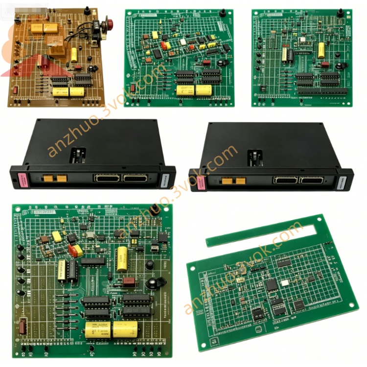
Product Type: Voltage Tester Card / Diagnostic Module
Application: Legacy Reliance drive systems (MaxPak Plus, VS Spindle, FlexPak 3000, GV3000)
Function: Precision in‑system voltage measurement, signal troubleshooting, calibration, and drive circuit validation
Status: Obsolete (discontinued); available as used / refurbished / new old stock
Warranty: 12 months (tested/refurbished units)
2. Electrical Specifications
Power Supply: +5 VDC, ±15 VDC (from drive backplane)
Measurement Ranges: AC/DC voltage, 0–600 VDC, 0–480 VAC
Input Impedance: >1 MΩ (high impedance, no circuit loading)
Accuracy: ±0.5% full scale
Isolation: 1000 VDC (test points to logic)
Front‑Panel Controls:
Large analog voltmeter (main display)
12‑position rotary switch (test point selection: 1–12)
Scale toggle switch: SCALE + / TEST –
Test signal potentiometer: TEST SIGNAL (0–10)
Protection: Overvoltage, transient, ESD, reverse polarity
3. Physical & Mechanical
Form Factor: Standard Reliance rack‑mount module
Dimensions (W×H×D): ~220 × 150 mm
Weight: ~0.8–1.0 kg
Front Panel: Analog meter, rotary switches, pots, test jacks
Connectors: Edge connector (backplane), front‑panel test ports
Construction: Industrial FR4 PCB, conformal coated; includes transformer, ICs, resistors, capacitors, diodes
4. Environmental Ratings
Operating Temperature: 0°C to +60°C
Storage Temperature: -20°C to +70°C
Humidity: 5%–95% RH, non‑condensing
Vibration: 10–150 Hz, 0.1 mm amplitude (cabinet rated)
5. Compatibility
Drive Systems: MaxPak Plus, VS Spindle Drives, FlexPak 3000, GV3000, AutoMax DCS
Related Modules: 0-51811-1 (older revision), 0-51805-5 (pulse input), 0-51772-3R (control board)
Replacement: Direct upgrade/replacement for 0-51811-1; improved accuracy and switching
6. Installation & Operation
Power Off: Disconnect all drive power before insertion/removal.
Rack Slot: Insert into dedicated drive rack slot; secure with retainers.
Backplane Power: Confirm +5 VDC and ±15 VDC at backplane connectors.
Test Point Selection: Use 12‑position switch to select drive signals (DC bus, control voltages, sensor inputs, I/O).
Scale Adjustment: Use SCALE + / TEST – toggle to match signal polarity/range.
Test Signal Generation: Adjust TEST SIGNAL pot to inject known voltage for calibration.
Meter Reading: Read AC/DC voltage directly from front‑panel analog meter.
7. Common Uses
Measure DC bus voltage (0–600 VDC)
Verify control circuit voltages (±15 VDC, +5 VDC)
Check tachometer/encoder signal levels
Troubleshoot I/O and sensor circuits
Calibrate drive feedback loops
Get a Quote