0-51419
Description
1. General Information
Manufacturer: Reliance Electric (Rockwell Automation / Baldor‑Reliance)
Part Number: 0‑51419 (051419)
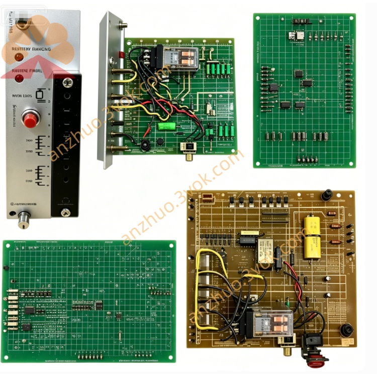
Product Type: Gate Couple Board / Gate Drive Interface Board
Application: Reliance ImPak Plus DC Drives (8C10/20/30) & related legacy DC drives
Function: Isolates, amplifies, and routes gate drive pulses from regulator board (0‑51381 series) to SCR power bridge; provides electrical isolation and pulse shaping for reliable SCR firing
Status: Obsolete (legacy replacement/repair part)
Warranty: 12 months (new/reconditioned)
Similar Models: 0‑51378 series, 0‑51418‑1 (gate drive variants)
2. Electrical Specifications
Control Power: ±12 VDC, +5 VDC (from 0‑51383 power supply)
Gate Drive Output: 4–6 channels, 15 V pulse @ 500 mA per channel (SCR gate trigger)
Pulse Isolation: 2500 VAC (control to power section)
Pulse Width: 10–20 µs (adjustable via on‑board trim)
Operating Frequency: 50/60 Hz (synchronized to line)
Protection: Overcurrent, short‑circuit, SCR fault detection
3. Physical & Mechanical
Dimensions (W×H×D): ~254 × 178 × 25 mm (10.0” × 7.0” × 1.0”)
Weight: ~0.68 kg (1.5 lbs)
Construction: Glass‑epoxy PCB, conformal coated, gold‑plated edge connectors
Mounting: Plug‑in into ImPak Plus card cage (vertical slot, adjacent to regulator board)
Key Components: Pulse transformers, opto‑isolators, power transistors, trim pots, fuses
4. Environmental Ratings
Operating Temperature: 0°C to +50°C (32°F to 122°F)
Storage Temperature: -20°C to +70°C (-4°F to 158°F)
Humidity: 5%–95% RH (non‑condensing)
Vibration: 0.15 mm p‑p @ 10–100 Hz
5. Key Features
High Isolation: 2500 VAC isolation protects low‑voltage logic from power circuit transients
Multi‑Channel Drive: 4–6 synchronized gate pulses for 3‑phase SCR bridges
Adjustable Pulse Width: On‑board trim pot optimizes SCR triggering
Fault Monitoring: Detects missing pulses or SCR short‑circuits; signals regulator board
Direct Replacement: Pin‑compatible with 0‑51378‑25/‑31 and 0‑51418‑1
6. Compatibility
DC Drives: ImPak Plus 8C10 (1–50 HP), 8C20 (50–200 HP), 8C30 (200–500 HP)
Associated Boards:
Regulator: 0‑51381‑11/‑13/‑16
Power Supply: 0‑51383‑2
Interface: 0‑51385
Replacement: Direct swap with 0‑51378‑31 (no wiring changes)
7. Installation & Maintenance
Installation
Disconnect all AC and control power to the drive.
Align board with card cage guides; insert firmly into edge connector.
Secure with mounting screws (if provided).
Verify pulse width setting (match drive manual recommendations).
Maintenance
Cleaning: Use dry, lint‑free cloth; avoid liquid cleaners.
Inspection: Quarterly check for burnt components, loose connections, or damaged pulse transformers.
Handling: Hold by edges; avoid touching connector pins or exposed circuitry.
8. Troubleshooting
No Drive Output: Check ±12 VDC power; verify on‑board fuses; test pulse transformers.
Intermittent Firing: Inspect for loose connections; adjust pulse width; check opto‑isolators.
SCR Overheating: Verify gate pulse amplitude/width; check for SCR gate leakage.
Fault Code Displayed: Check for missing pulses; test wiring to SCR gates; replace board if faulty.
Get a Quote