0-49067
Description
Basic Information
Manufacturer: Reliance Electric (Rockwell Automation)
Part Number: 0-49067 (alternate: 049067)
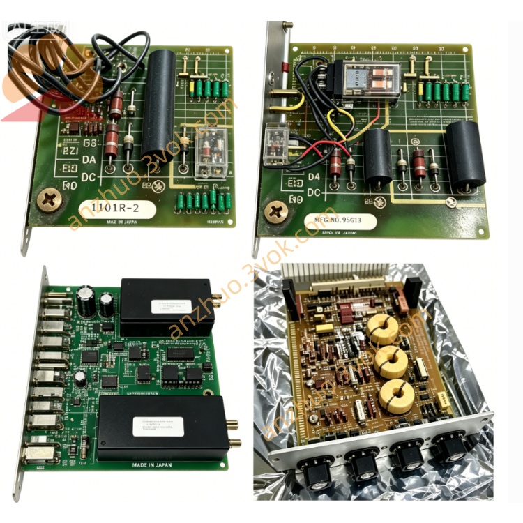
Type: Auxiliary Function Control Card
Series: CardPak (legacy DC drive system)
Function: Signal conditioning, auxiliary regulation & interlock logic for DC drive control loops
Status: Obsolete / Discontinued (spare parts only; used/surplus available)
Electrical Specifications
Inputs: ±10 VDC analog signals, dry contact interlocks
Outputs: ±10 VDC conditioned signals, relay contacts (NO/NC)
Control Power: +5 VDC, ±15 VDC (CardPak bus)
Signal Accuracy: ±0.2% FSR
Bandwidth: DC to 10 kHz
Isolation: Galvanic isolation (I/O ↔ logic ground)
Protection: Overvoltage, short-circuit, thermal shutdown
Mechanical & Environmental
Mounting: Standard CardPak slot-mount (slide-in + front-panel screw)
Dimensions (L×W×H): 305 × 254 × 203 mm (12 × 10 × 8 in)
Weight: Approx. 1.4 kg (3.0 lbs)
Operating Temp: 0°C to 50°C (32°F to 122°F)
Storage Temp: -20°C to 60°C (-4°F to 140°F)
Humidity: 5%–95% non-condensing
Key Features
Multi-Function Signal Processing: Scaling, offset, filtering for analog loops
Interlock & Safety Logic: Hardware-based fault interlocks (overcurrent, overtemperature)
Front-Panel Adjustments: Potentiometers for gain, offset, threshold
LED Status Indicators: Power, Run, Fault, Signal Activity
Industrial Durability: Vibration/noise immunity for harsh factory environments
Compatible Modules
System Pairs: 0-49040-2 (Rectifier Firing), 0-49042-1 (Power Amp), 0-49060-1 (Current Summing), 0-49061 (Square Wave Gen)
Chassis: All CardPak DC drive chassis (VS Series, MaxPak compatible)
Installation & Adjustment
Installation
De-energize the entire drive system.
Insert 0-49067 into a free CardPak slot; tighten front-panel screws.
Verify edge connectors are fully seated; check +5 VDC/±15 VDC bus power.
Calibration
Power on; confirm Power LED is ON.
Apply reference input; adjust Gain pot for target output amplitude.
Set input to zero; adjust Offset pot for 0 VDC output.
Test interlock thresholds; adjust Threshold pot for fault trigger points.
Lock potentiometers; validate loop stability under load.
Operation & Faults
Normal: Power/Run LEDs ON; clean output signal; no fault triggers.
Fault LED ON: Overvoltage, short circuit, thermal trip, or interlock activation (reset after clearing fault).
No Output: Check bus power, wiring, on-board fuse, or input signal presence.
Get a Quote