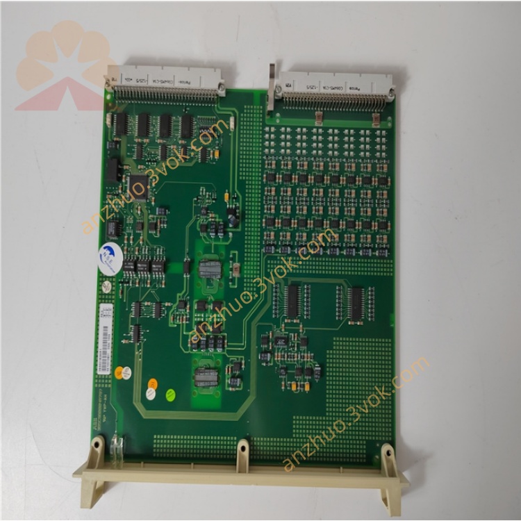
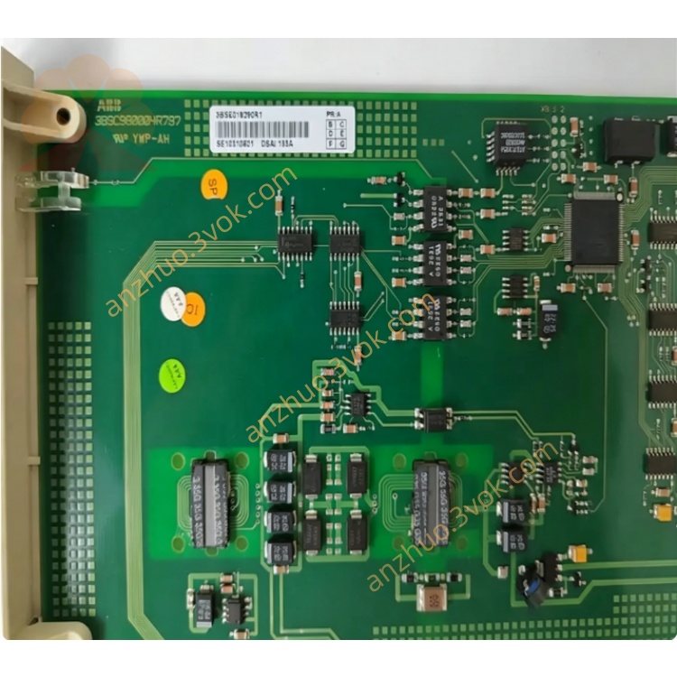
ABB DSAI133A 3BSE018290R1 Analog Input Module
Description
Product Overview
DSAI133A (3BSE018290R1) is a 32-channel analog input board of the S100 series in the ABB Advant OCS / 800xA system, used for collecting industrial standard analog signals such as 4–20mA and 0–10V, and converting them into digital quantities for processing by the DCS.
Technical Specifications (Core)
Channels: 32 independent configurable analog inputs
Signal Types: Current (4–20mA), Voltage (0–10V / ±10V)
Resolution: 16 bits
Accuracy: ±0.2% of full scale
Isolation: Electrical isolation between channels, strong anti-interference
Power Supply: 24VDC ±20%, maximum 5mA
Dimensions (Depth × Height × Width): 324×22.5×225mm; Weight: 0.29kg
Operating Temperature: -20°C ~ +60°C; Installation Method: DIN rail
??️ Installation Steps
Environmental Check: IP20 protection, away from strong electromagnetic interference (frequency converter, large motor), good ventilation.
Rail Installation: Module inserts into standard DIN rail, lock in tightening screws to ensure no looseness.
System Adaptation: Insert into S100 I/O rack, confirm compatibility with controller (AC450/AC800M) firmware version.
Grounding Requirements: Module ground is reliably connected to system ground, grounding resistance < 4Ω, avoid ground circulation.
?? Wiring Guide (Terminal Definitions)
Power Terminals:
+24V: Positive pole of DC 24V
0V: Negative pole of DC 24V
PE: Protective ground
Signal Terminals (Single Channel Example):
CHx+: Positive terminal of signal (4–20mA / 0–10V)
CHx-: Negative terminal of signal (common ground)
Connection Points:
Current Signal: Two-wire system (+24V → transmitter → CHx+ → CHx- → 0V)
Voltage Signal: Three-wire system (signal +, signal -, shield ground)
Shield Layer: Single-ended grounding (control cabinet side), avoid double-ended grounding introducing interference.
?? Software Configuration (800xA / Advant OCS)
Hardware Identification: System automatically scans I/O rack, identifies DSAI133A, confirms address (e.g. Slot 5).
Channel Parameter Settings (Independent for Each Channel):
Signal Type: Select 4–20mA or 0–10V
Range: 4–20mA corresponds to 0–100%; 0–10V corresponds to 0–1000
Filtering: Digital filtering (100ms), suppresses high-frequency interference
Calibration: Enable self-calibration to eliminate drift
Downloading and Verification: Parameters are downloaded to the module, real-time values of channels are viewed online to confirm normal signals.
?? Troubleshooting (Common Issues)
No Signal (Channel Value is 0)
Check: Is the 24V power supply normal; Is the wiring loose / reversed; Is the transmitter powered normally?
Solution: Reconnect the wiring, measure the terminal voltage, replace the faulty transmitter.
Large Signal Fluctuation
Check: Is the shield layer double-ended grounded; Are there any frequency converters / large motors nearby causing interference; Is the filtering time too short?
Solution: Single-ended grounding, increase filtering time (500ms), stay away from interference sources.
Module Error (Red Light On)
Check: Is the module and rack not in good contact; Is the firmware version incompatible; Is the channel short-circuited?
Solution: Reinsert the module, upgrade the firmware, check if there is a short circuit in the wiring.
?? Maintenance and Care
Regularly (every 6 months): Check if the terminal connections are tight and not loose; Dust off the module surface; Ensure reliable grounding connection.
Calibration (once a year): Use a standard signal source (4–20mA / 0–10V) to calibrate channel accuracy, record calibration data.
Life Cycle: The module is a legacy product (has been discontinued), it is recommended to have a redundant backup machine to avoid downtime risks.
⚠️ Safety Precautions
Before installation / wiring, power must be disconnected to prevent electric shock or module damage.
Do not plug or unplug the module while powered on, to avoid burning the interface chip. The signal cables and power cables are laid separately (with a distance of more than 30 cm), reducing interference.
Get a Quote