6200055
Description
2. Main Features
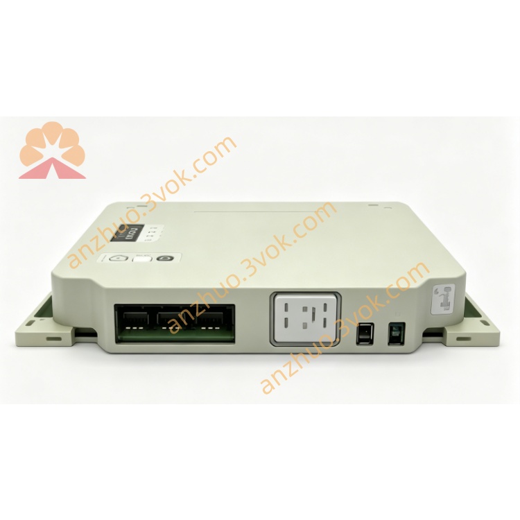
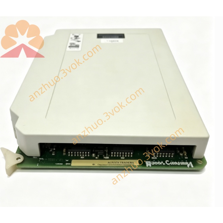
Model: 6200055
Type: Inductive proximity sensor
Detection target: All metal materials
Supply voltage: 10–30 V DC
Output mode: 3-wire DC
Max load current: ≤ 200 mA
Protection grade: IP67 dustproof and waterproof
Working temperature: -25 °C ~ +70 °C
Built-in reverse polarity, overvoltage and short-circuit protection
Vibration resistant, shockproof, suitable for long-term continuous operation
3. Safety Precautions
Cut off power supply before installation and wiring.
Do not exceed rated voltage 10–30 V DC.
Reverse power connection is strictly prohibited to avoid sensor damage.
Install away from high-power motors, transformers and strong magnetic field interference.
Do not disassemble or modify the sensor structure arbitrarily.
Avoid heavy mechanical impact, oil corrosion and long-term wet environment.
4. Installation Guide
Fix the sensor with lock nut or mounting bracket.
Maintain the rated sensing distance from the metal target.
Mount perpendicular to the detected surface to ensure detection accuracy.
Do not place redundant metal parts near the sensing head.
Arrange cable routing properly, avoid sharp bending and forced pulling.
5. Wiring Definition
Brown : DC +10~30 V Power
Blue : DC 0 V Ground
Black : Signal output
Shield : Ground only at controller end
6. Operating Instructions
Complete wiring strictly in accordance with the definition.
Power on, sensor enters standby working state.
When metal object enters effective sensing range, indicator lights up and output signal acts.
When metal target leaves, output resets and indicator turns off.
It can be directly matched with PLC, relay and industrial controller input.
7. Troubleshooting
No indicator light: Check power supply and wiring circuit.
Always output signal: Metal target too close or ambient metal interference.
Signal flickering unstably: Loose wiring, mechanical vibration or power fluctuation.
Indicator on but no output: Signal wire breakage or load damage.
8. Maintenance
Regularly clean dust and iron debris on the sensing surface with dry cloth.
Periodically check mounting tightness and cable wear condition.
Avoid long-term operation in high temperature and corrosive gas environment.
Replace the sensor in time if shell crack or cable aging appears.
2. Main Features
Model: 6200055
Type: Inductive proximity sensor
Detection target: All metal materials
Supply voltage: 10–30 V DC
Output mode: 3-wire DC
Max load current: ≤ 200 mA
Protection grade: IP67 dustproof and waterproof
Working temperature: -25 °C ~ +70 °C
Built-in reverse polarity, overvoltage and short-circuit protection
Vibration resistant, shockproof, suitable for long-term continuous operation
3. Safety Precautions
Cut off power supply before installation and wiring.
Do not exceed rated voltage 10–30 V DC.
Reverse power connection is strictly prohibited to avoid sensor damage.
Install away from high-power motors, transformers and strong magnetic field interference.
Do not disassemble or modify the sensor structure arbitrarily.
Avoid heavy mechanical impact, oil corrosion and long-term wet environment.
4. Installation Guide
Fix the sensor with lock nut or mounting bracket.
Maintain the rated sensing distance from the metal target.
Mount perpendicular to the detected surface to ensure detection accuracy.
Do not place redundant metal parts near the sensing head.
Arrange cable routing properly, avoid sharp bending and forced pulling.
5. Wiring Definition
Brown : DC +10~30 V Power
Blue : DC 0 V Ground
Black : Signal output
Shield : Ground only at controller end
6. Operating Instructions
Complete wiring strictly in accordance with the definition.
Power on, sensor enters standby working state.
When metal object enters effective sensing range, indicator lights up and output signal acts.
When metal target leaves, output resets and indicator turns off.
It can be directly matched with PLC, relay and industrial controller input.
7. Troubleshooting
No indicator light: Check power supply and wiring circuit.
Always output signal: Metal target too close or ambient metal interference.
Signal flickering unstably: Loose wiring, mechanical vibration or power fluctuation.
Indicator on but no output: Signal wire breakage or load damage.
8. Maintenance
Regularly clean dust and iron debris on the sensing surface with dry cloth.
Periodically check mounting tightness and cable wear condition.
Avoid long-term operation in high temperature and corrosive gas environment.
Replace the sensor in time if shell crack or cable aging appears.
Get a Quote