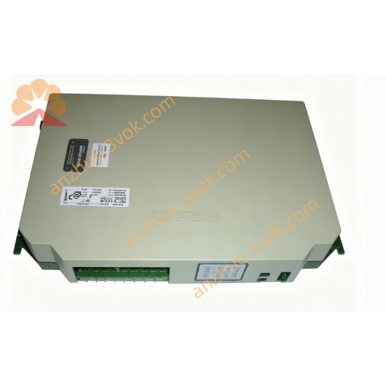
6200027
Description
2. Main Features
Model: 6200027
Working principle: Inductive magnetic induction
Detected object: All metal materials
Supply voltage: 10–30 V DC
Output type: 3-wire DC
Maximum load current: ≤ 200 mA
Protection grade: IP67 dustproof and waterproof
Operating temperature: -25 °C ~ +70 °C
Built-in reverse polarity and short circuit protection
Vibration resistant and industrial high stability design
3. Safety Precautions
Disconnect power before installation and wiring.
Do not exceed rated voltage 10–30 V DC.
Strictly forbid reverse power wiring to avoid burnout.
Keep away from motors, transformers and strong magnetic interference sources.
Do not disassemble or modify the sensor structure.
Prevent mechanical impact, oil corrosion and long-term water soaking.
4. Installation Instructions
Fix the sensor with standard nut or mounting bracket.
Keep proper detection distance from metal target.
Install perpendicular to the detected surface for optimal sensitivity.
Do not place extra metal parts around the sensing head.
Arrange cable routing reasonably, avoid sharp bending and pulling.
5. Wiring Definition
Brown:DC +10~30 V Power Positive
Blue:DC 0 V Ground
Black:Signal Output
Shield wire:Ground only at controller end
6. Operation Guide
Wire connection must follow the standard definition.
Power on, sensor enters standby state.
When metal enters effective sensing range, indicator light turns on and output signal activates.
When metal leaves the detection area, output resets and indicator turns off.
Can be directly connected to PLC, relay and automation controller input.
7. Fault Troubleshooting
No indicator light: Check power supply and wiring integrity.
Always output signal: Metal target too close or peripheral metal interference.
Signal flickering: Loose wiring, equipment vibration or unstable power.
Light on but no output: Signal line broken or load failure.
8. Daily Maintenance
Regularly wipe sensing surface to remove dust and iron debris.
Periodically check mounting tightness and cable wear condition.
Avoid long-term high temperature and corrosive gas environment.
Replace immediately if shell damage or cable aging occurs.
Get a Quote