1010521
Description
2. Key Features
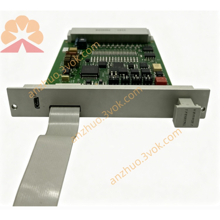
Model: 10105/2/1 (1010521)
Type: Fail‑safe analog input module
Channels: 16 isolated analog input channels
Input Ranges: 0–4.1 V (standard); supports 4–20 mA, 0–10 V via external circuitry
Resolution: 12‑bit A/D converter
Accuracy: < ±0.25% full scale
Safety: IEC 61508 SIL 3 compliant (FSC system)
Power: 5 V DC (35 mA); 24 V DC (35 mA)
Communication: FSC system bus (proprietary)
Operating Temp: –20 °C to +60 °C
Certifications: CE, ATEX, IECEx (safety)
3. Safety Precautions
Disconnect 5 V DC and 24 V DC power before installation, wiring, or maintenance.
Install in a FSC 19‑inch rack with proper grounding (safety earth).
Separate analog signal cables from high‑voltage/power cables to avoid EMI/RFI interference.
Only qualified safety automation personnel may install, configure, or replace the module.
Do not open or modify the module; no user‑serviceable parts inside.
For SIL 3 applications, maintain redundant module configuration and periodic proof tests.
4. Installation
4.1 Rack Mounting
Insert the module into a standard FSC 19‑inch rack slot (single‑width).
Align with the backplane connector, push firmly, and tighten front panel screws.
For redundancy, install a second 10105/2/1 in the adjacent slot (if required).
Ensure airflow; avoid blocking ventilation holes on the module/rack.
4.2 Terminal Wiring (Field Connections)
CH01–CH16: Analog input channels (0–4.1 V, 4–20 mA, or 0–10 V)
COM: Common ground for analog inputs
+24 V: 24 V DC power (module supply)
+5 V: 5 V DC power (logic supply, from backplane)
GND: System ground (safety earth)
5. Front Panel Indicators
PWR (Green): ON = 5 V/24 V power normal; OFF = power fault
RUN (Green): ON = module active/online; Blinking = self‑test/boot
ERR (Red): ON = safety fault; Blinking = minor alarm (e.g., channel error)
CH01–CH16 (Yellow): ON = channel active; Blinking = input fault (e.g., open/short)
6. Basic Operation
Power‑On & Self‑Test
Apply 5 V DC (backplane) and 24 V DC power.
Module performs self‑test (~30 seconds): RUN blinks, ERR off.
After successful test: RUN steady green; module enters safety run mode.
Each channel (CH01–CH16) initializes; yellow LEDs light for active channels.
Configuration
Use Honeywell FSC Navigator Software (R5xx/R600) or FSC Development System (R42x).
Connect to the FSC system via engineering workstation.
Set input type (voltage/current), range, scaling, and fault thresholds.
Download configuration to the module; save to non‑volatile memory.
7. Main Parameters
Input Impedance: > 1 MΩ (voltage); 250 Ω (4–20 mA)
Update Rate: 100 ms per channel (configurable)
Fault Detection: Open/short circuit, over‑range, under‑range
Default Range: 0–4.1 V (0–20 mA with external 250 Ω resistor)
Isolation: 500 V AC between channels and system ground
8. Fault & Error Codes
E01: 24 V DC power fault (check wiring/supply)
E02: 5 V DC backplane fault (check rack/power supply)
E03: System bus communication loss (check backplane/CPU)
E04: Channel over‑range (check sensor/input signal)
E05: Channel open/short circuit (check field wiring)
E06: Module overheating (check ventilation/ambient temp)
9. Specifications
Model: 10105/2/1 (1010521)
Type: Fail‑safe high‑density analog input module
Channels: 16 isolated inputs
Input Ranges: 0–4.1 V (standard); 4–20 mA, 0–10 V (optional)
Resolution: 12‑bit
Accuracy: < ±0.25% FS
Power: 5 V DC (35 mA); 24 V DC (35 mA)
Operating Temp: –20 °C to +60 °C
Humidity: 10–90% RH (non‑condensing)
Dimensions: 130 × 482 × 30 mm (single‑width, 19‑inch rack)
Weight: Approx. 0.8 kg
Certifications: CE, ATEX, IECEx, SIL 3
10. Maintenance
Keep rack and module clean; avoid dust, moisture, and corrosive gases.
Check power cables and backplane connections monthly for tightness.
Verify field wiring (analog cables) quarterly for damage/loose terminals.
Back up module configuration every 6 months.
Perform proof test annually for SIL 3 applications (per IEC 61511).
Get a Quote