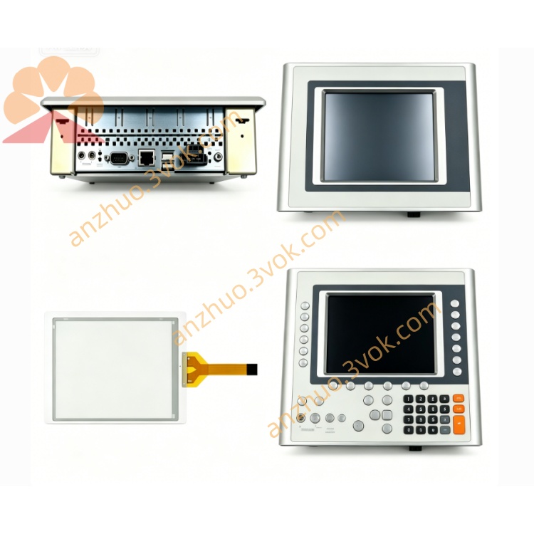
Product Description for B&R 7CP470.60-1 Slot Installation Specification
Description
Product Description for B&R 7CP470.60-1 Slot Installation Specification
1. Slot Position Definition on System 2003 Backplane
Slot 1: Exclusive dedicated position for CPU (7CP470.60-1, 7CP430.60-1 and other System 2003 CPUs), fixed as backplane bus master;
Slot 2, Slot 3, Slot 4 and subsequent positions: Slave expansion slots for analog I/O, digital I/O, counter modules and communication modules like 7CM411.70-1;
It cannot be inserted into slave expansion slots; installing the CPU into non-first slot will cause backplane bus initialization failure, no system startup and persistent FAULT alarm.
2. Mechanical Slot Structure & Locking Mechanism
2.1 Slot Contact Structure
Master slot (Slot1) has complete CPU bus signal pins including power supply, backplane differential communication, RTC backup signal;
Slave slots only contain slave bus signal pins without master control circuit contacts;
All contact pins are corrosion-resistant gold plating, designed for long-term plug and vibration resistance in industrial cabinets.
2.2 Module Snap Lock for Slot Fixing
Locked state: No horizontal shaking or loose contact under equipment vibration;
Unlocking: Lift the snap buckle upward vertically, then pull the CPU straight out horizontally, no tilting or forced prying to avoid bending contact pins inside the slot.
2.3 Slot Physical Dimension
3. Slot Electrical Matching Rules
Power supply distribution: Slot 1 receives 24 V DC power from the backplane internal power bus first, then distributes power sequentially to each slave slot behind it; poor CPU slot contact will lead to power loss for the entire rack.
Backplane bus master authorization: Only Slot 1 hardware circuit enables the CPU master bus controller; slave slots are hard-defined as bus slave nodes, unable to host CPU master functions.
Isolation protection: Each slot has independent transient surge protection circuits; short circuit or reverse wiring in one expansion slot will not directly damage the CPU master slot circuit.
Signal transmission: Differential bus signals run through all slots in series, with Slot1 CPU as the signal source for cyclic polling of all slave modules in subsequent slots.
4. Unused Slot Handling Requirements
Stabilize backplane bus impedance to prevent signal reflection, bus jitter and communication frame loss;
Block dust, metal debris and moisture from entering empty slots to avoid pin oxidation, short circuit and contact degradation;
Maintain consistent cabinet air convection heat dissipation for the whole rack.
Leaving slots uncovered long-term will gradually reduce communication stability between CPU and expansion modules such as 7CM411.70-1.
5. Slot Installation Step-by-Step Operation
Confirm the 7BP backplane is securely fixed on standard 35 mm DIN rail inside the control cabinet and rack power is fully cut off;
Lift the CPU’s bottom snap lock upward to open the locking position;
Align the PCB gold-plated plug of 7CP470.60-1 horizontally with Slot1 master slot opening, push steadily and evenly until the module front panel is fully attached to the backplane surface;
Press down the snap lock firmly to clamp the module onto the backplane slot and DIN rail;
Install analog I/O, digital I/O and 7CM communication modules into Slot2, Slot3 and other slave slots in sequence, lock each module’s buckle one by one;
Cover all remaining empty slots with 7AC020.9 blank baffles;
Restore rack 24 V power supply, check CPU front panel LEDs: POWER light on, BUS light steady, no FAULT alarm to confirm Slot1 contact and bus initialization are normal.
6. Fault Phenomena Caused by Abnormal Slot Status
CPU inserted into wrong slave slot: POWER LED may light up briefly, BUS flashes irregularly, FAULT stays on, system cannot enter RUN mode, no backplane module identification;
Loose CPU Slot1 lock: Intermittent BUS disconnection, random fault alarms, occasional program crash or I/O signal loss;
Dirty/oxidized Slot1 contact pins: Weak communication, slow program download speed, unstable RTC time keeping;
Empty slots without baffles: Gradual increase of bus interference, abnormal data fluctuation of analog I/O and delayed response of servo axes connected via 7CM modules.
7. Compatible Hardware & Environmental Limits
8. Maintenance Notes for Master Slot (Slot1)
When removing 7CP470.60-1 from Slot1, always cut off rack power first to prevent hot plug-induced surge damage to CPU and backplane slot circuits;
If contact pins in Slot1 are dusty or slightly oxidized, clean gently with dedicated contact cleaner and soft lint-free cloth, never use metal tools to scrape pins;
Do not repeatedly plug and unplug the CPU into Slot1 frequently; excessive plug times will wear gold plating and shorten service life of slot contacts;
During spare CPU storage, protect the bottom PCB plug with a dust cap to prevent pin oxidation before installation into Slot1.
Get a Quote