Product Description for B&R 7CM211.7 Function Communication Module (System 2003 Platform)
1. Product Overview
7CM211.7 is a dedicated plug-in communication function module developed exclusively for B&R System 2003 PCC automation control system, it is not analog/digital mixed I/O module, its core function is fieldbus data interaction. Made in Austria following European industrial standards, it inserts into the slot of 7BP series System 2003 backplane, and realizes high-speed data exchange with host CPU through System 2003 proprietary internal backplane bus. The whole System 2003 hardware series has been officially end-of-life by B&R. Available stock includes original new imported modules and fully inspected refurbished units, used for legacy production line maintenance, equipment transformation and emergency spare replacement. Built-in electrical isolation and anti-surge drive circuits can resist strong electromagnetic interference from inverters, servo drives and contactors inside control cabinets, with CE and UL/cULus industrial safety certifications.
2. Basic Product Information
Official part number: 7CM211.7, category: System 2003 standard pluggable communication function submodule.
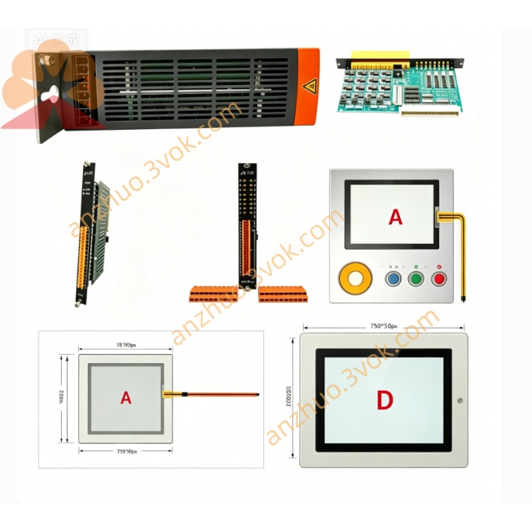
Integrated compact unit with built-in screw terminal block for fieldbus wiring, no extra external signal conversion adapter required. Laser marking on flame-retardant plastic housing contains B&R logo, complete part code, hardware revision, unique serial number and Austrian production batch code for full supply chain traceability and genuine verification.
24 V DC working power is taken directly from backplane slot, no independent external power supply needed. Unified mechanical size matches all System 2003 pluggable hardware, compatible with all 7BP backplane models (7BP701.1,7BP702.0,7BP703.0,7BP704.0,7BP707.0,7BP708.0,7BP709.0,7BP710.0).
Multiple LED status lights on front panel intuitively display module power, internal backplane bus link, external bus communication running state and fault alarm information for fast on-site troubleshooting.
3. Core Functional Description
3.1 Internal Bus Communication Function
Stable connection with System 2003 host CPU via proprietary backplane bus, real-time transmission of configuration instructions, real-time process data and fault diagnosis data, synchronous data interaction without obvious transmission delay.
3.2 External Fieldbus Gateway Function
Acts as protocol conversion bridge between local control station and external industrial equipment:
Upload: Transmit real-time production data, equipment running status, overheat/overload fault signals from local PCC to upper HMI, SCADA monitoring system or master controller;
Download: Receive operation set values, motion control commands, equipment parameter groups issued by upper system and transmit them to local System 2003 controller for execution.
3.3 Multi-network Expansion Function
Multiple 7CM211.7 function modules can be installed on one backplane at the same time, realizing multiple independent external bus channels, suitable for distributed control systems with multi-brand drives, multi-group monitoring hosts.
3.4 Isolation Anti-interference Function
Built-in galvanic isolation circuit between internal and external bus, effectively eliminate ground loop potential difference interference; matched with overvoltage, overcurrent and reverse wiring protection to avoid field wiring faults burning internal control circuits.
3.5 Software Configuration Function
All communication parameters (station address, baud rate, communication protocol type, data length) are uniformly set, compiled and downloaded through B&R Automation Studio software, no hardware jumper or potentiometer adjustment required on the module body.
4. Performance & Structural Parameters
Isolation performance: Complete galvanic isolation between internal bus and external fieldbus
Internal bus: B&R exclusive System 2003 high-speed proprietary bus protocol
Protection level: IP20 when installed in sealed indoor electrical control cabinet
Operating ambient temperature: 0 ℃ ~ +60 ℃
Storage & transport temperature: -25 ℃ ~ +70 ℃
Power supply: 24 V DC supplied by backplane, low power consumption, small load to rack power supply
Wiring interface: Standard screw terminals, support shielded twisted-pair communication cables
Firmware scheduling: No independent running firmware; all communication logic and protocol stacks are managed by System 2003 CPU program
5. Compatible Matching Hardware
7CM211.7 only adapts to B&R System 2003 hardware ecosystem, cannot match X20, X67, APC, ACOPOS and other new-generation platforms.
Full compatible supporting parts:
7CP series System 2003 PCC CPU main modules
All 7BP series rack backplanes
7AF104.7 analog adapter bases and 7AI/7AM/7AO/7AT analog submodules
System 2003 digital I/O modules, 7AC020.9 blank slot covers, dedicated 24 V DC rack power supplies
Accessory requirement: Shielded twisted-pair cables must be used for external bus wiring to reduce electromagnetic interference.
6. Applicable Industries & Equipment
Widely equipped on automation control stations built with System 2003 architecture: plastic injection molding machines, packaging filling lines, textile drying & winding equipment, CNC metal cutting machine tools, printing presses, multi-station automated assembly machines, food thermal processing equipment, municipal water treatment pump control cabinets, heavy-duty material conveyor control systems.
Installation environment: Only for IP20 indoor electrical cabinets fixed on standard DIN rails in factory workshops and sheltered semi-outdoor equipment rooms; not applicable to corrosive gas, high humidity, flammable explosive or fully open outdoor environments without sealed protective cabinets.
7. Quality and After-supply Instructions
Genuine 7CM211.7 function modules have unique factory serial numbers archived in B&R Austrian production database for full traceability. Since System 2003 platform is discontinued, products are supplied only by authorized global industrial spare part distributors.
Refurbished modules pass strict pre-delivery full test: plug contact continuity, isolation circuit performance, CPU communication compatibility, LED indicator function, surge protection reliability. Qualified refurbished units carry 12–24 months standard supplier warranty.
Standard commissioning steps: Insert module into vacant backplane slot → Wire shielded fieldbus cables to terminals → Configure communication parameters in Automation Studio and download to CPU → Confirm normal link and data transmission via front LED indicators.
It is strictly prohibited to disassemble internal PCB or modify onboard circuits without authorization during installation and maintenance. Long-term storage needs dry, constant-temperature low-humidity warehouse to prevent terminal oxidation and plastic shell aging. When replacing spare parts, technicians need to confirm mechanical slot size and System 2003 bus protocol compatibility with on-site existing hardware.
Get a Quote