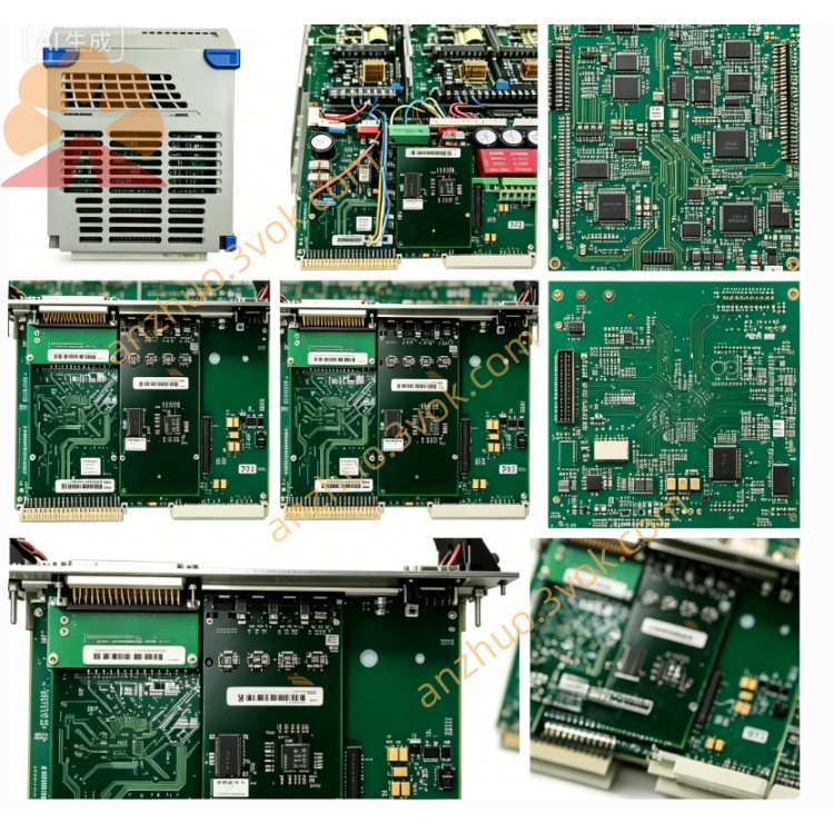
405A720H05 – Power Supply Module
Description
1. Product Overview
2. Key Specifications
2.1 General
Part Number: 405A720H05
Manufacturer: Westinghouse / Emerson
Product Type: Multibus Power Supply Module
Compatible Systems: WDPF DCS, Ovation DCS (all chassis: 405A675G / 405A685G series)
Revision: H05 (latest production revision)
Status: Obsolete (EOL);available as NOS (New Old Stock) or certified refurbished
Warranty: 12 months (refurbished);24 months (NOS)
2.2 Electrical
Input Voltage: 100–240 VAC ±10%, 50/60 Hz (auto‑ranging, no switch required)
Input Power: 350 VA max
Output Voltages (Multibus standard):
+5 VDC: 25 A (125 W)
+12 VDC: 6 A (72 W)
−12 VDC: 3 A (36 W)
Regulation: ±0.3% (full load, line variation)
Ripple & Noise: < 30 mV p‑p
Protection: OVP, OCP, SCP, OTP, inrush current limiting
Efficiency: > 90% at full load (230 VAC input)
Power Factor: > 0.95 (active PFC)
2.3 Physical
Form Factor: Standard 6U DCS module
Dimensions (W×H×D): 305 mm × 203 mm × 25 mm (12.0 in × 8.0 in × 1.0 in)
Weight: ≈ 1.3 kg (2.9 lb)
Mounting: 12‑slot Multibus chassis
Connectors: Multibus edge connector (backplane), screw terminal block (AC input)
Coating: Conformal coated (dust, moisture, corrosion resistance)
Cooling: Forced air (chassis fan)
2.4 Environmental
Operating Temperature: 0 °C to +60 °C (32 °F to 140 °F)
Storage Temperature: −40 °C to +85 °C (−40 °F to 185 °F)
Relative Humidity: 5% to 95% (non‑condensing)
Shock/Vibration: IEC 60068‑2‑6 compliant
MTBF: > 120,000 hours (25 °C, full load)
3. Main Features
- Latest Revision Performance
H05 PCB with enhanced thermal design and high‑grade components; updated firmware for improved stability.
- Higher Output Power & Efficiency
25 A +5 VDC output (vs. 20 A on H03); >90% efficiency reduces heat and energy costs.
- Advanced Protection Suite
OVP/OCP/SCP/OTP with auto‑recovery; inrush current limiting protects chassis backplane.
- Hot‑Swap & Redundancy Optimized
Supports seamless online replacement in redundant Ovation/WDPF systems; no shutdown required.
- Improved Diagnostics
Front‑panel LEDs with enhanced fault indication; supports remote alarm monitoring (system‑dependent).
- Full Backward Compatibility
Direct replacement for 405A720H01/H02/H03; no chassis or software changes needed.
4. Applications
Power Generation: Thermal, nuclear, combined‑cycle plants (WDPF/Ovation DCS).
Process Industries: Petrochemical, pulp & paper, cement, water treatment, pharmaceutical.
DCS Upgrades: Preferred replacement for aging H03 power supplies in legacy Multibus chassis.
High‑Availability Systems: Redundant power configurations for 24/7 operation.
5. Comparison with 405A720H03
| Feature | 405A720H05 | 405A720H03 |
|---|---|---|
| Output +5 VDC | 25 A | 20 A |
| Efficiency | >90% | >85% |
| Regulation | ±0.3% | ±0.5% |
| Ripple | <30 mV | <50 mV |
| MTBF | >120,000 h | >100,000 h |
| Protection | OVP/OCP/SCP/OTP + inrush limit | OVP/OCP/SCP/OTP |
| Compatibility | All WDPF/Ovation | Most WDPF/Ovation |
6. Installation Instructions
6.1 Pre‑Installation Safety
ESD Protection: Always use an ESD wristband when handling the module.
Power Off: Shut down the DCS chassis; disconnect AC input; wait 5 minutes for capacitors to discharge.
Inspection: Check for bent pins, damaged connectors, or physical damage.
6.2 Installation Steps
Select Slot: Choose an available 6U Multibus slot in the 405A675G/685G chassis.
Insert Module: Align with chassis guides; insert firmly until fully seated in the backplane.
Secure Module: Tighten the front‑panel screw to ensure grounding and mechanical stability.
Connect AC Input: Wire 100–240 VAC to the terminal block (L = Line, N = Neutral, PE = Protective Earth).
Power On: Reconnect AC power; verify LED status: PWR (Green) ON, OUT (Yellow) ON.
Verify Output: Measure +5 VDC (±0.3%) and ±12 VDC at backplane test points.
7. LED Indicators
| LED | Color | Status | Description |
|---|---|---|---|
| PWR | Green | ON | AC input present, standby power normal. |
| OUT | Yellow | ON | All DC outputs within regulation (normal operation). |
| FLT | Red | ON | Fault: OVP/OCP/SCP/OTP; check load or replace module. |
| FLT | Red | Blinking | Over temperature; check chassis airflow and fans. |
8. Maintenance & Troubleshooting
8.1 Preventive Maintenance (Quarterly)
Visual Inspection: Check connectors for dirt, corrosion, or loose wiring.
Cleaning: Use dry, low‑pressure compressed air (≤ 2 bar) to clean vents and components.
Load Test: Verify output voltages under full load; compare to specifications.
Cable Check: Inspect AC input cable for damage; replace if worn.
8.2 Troubleshooting
PWR LED OFF: Check AC input, fuse, terminal block wiring, and chassis circuit breaker.
OUT LED OFF:
Disconnect all I/O modules; power on to test if fault persists.
If fault clears, reconnect modules one by one to isolate the faulty load.
If fault remains, replace 405A720H05.
FLT LED ON:
Check for short circuits in wiring or modules.
Verify input voltage is within 100–240 VAC range.
Replace module if fault persists.
Blinking FLT LED: Ensure chassis fans are operational; clear blocked vents; reduce ambient temperature.
9. Storage & Handling
Packaging: Store in original anti‑static packaging; keep in a cool, dry, dust‑free area.
Temperature: −40 °C to +85 °C; avoid direct sunlight and heat sources.
Handling: Hold the module by the edges only; avoid touching components or connectors.
Transport: Use shock‑absorbent packaging; avoid heavy vibration during shipping.
Get a Quote