405A689G04
Description
1. Product Overview
2. Key Specifications
2.1 General
Part Number: 405A689G04
Manufacturer: Westinghouse / Emerson
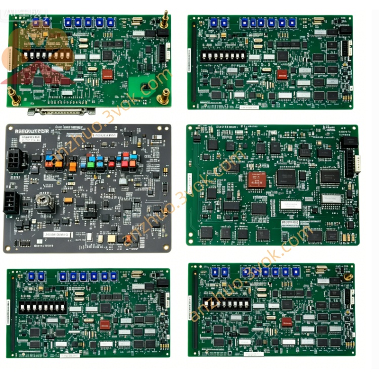
Product Type: SMS 8007 Disk Controller Board
Compatible Systems: WDPF DCS, Ovation DCS
Revision: Rev 7 (final production revision)
Status: Obsolete (EOL);available as NOS (New Old Stock) or refurbished
Warranty: 12 months (refurbished);24 months (NOS)
2.2 Electrical
Power Supply: +5 VDC (±5%), ±12 VDC (±10%) from Multibus backplane
Power Consumption: ≈ 4.2 W (operating)
Bus Interface: Multibus I (WDPF/Ovation backplane compliant)
Onboard Memory: 128 KB ECC RAM (error‑correcting code)
Storage Interface: SCSI‑1 (50‑pin internal connector)
2.3 Physical
Dimensions (W×H×D): Standard 6U DCS module – 305 mm × 203 mm × 25 mm (12.0 in × 8.0 in × 1.0 in)
Weight: ≈ 0.55 kg (1.2 lb)
Mounting: 12‑slot Multibus chassis (405A675G / 405A685G series)
Coating: Conformal coated (protection against dust, moisture, corrosion)
2.4 Environmental
Operating Temperature: 0 °C to +60 °C (32 °F to 140 °F)
Storage Temperature: −40 °C to +85 °C (−40 °F to 185 °F)
Relative Humidity: 5% to 95% (non‑condensing)
Shock/Vibration: Industrial‑grade (compliant with IEC 60068‑2‑6)
3. Main Features
- Latest Revision Hardware/Firmware
Rev 7 PCB with improved trace routing and component quality.
Updated SMS 8007 firmware (v4.2) fixing G01/G03 bugs; better compatibility with SSD‑based disk emulators.
- Enhanced ECC Memory
128 KB ECC RAM detects and corrects single‑bit errors; prevents data corruption in high‑noise industrial environments.
- Full Backward Compatibility
Drop‑in replacement for 405A689G01/G03; no chassis or software modifications required.
- Hot‑Swap Capable
Supports online replacement in redundant WDPF/Ovation systems; no shutdown required (system‑dependent).
- Robust Industrial Design
Conformal coating, extended temperature range, and vibration resistance for 24/7 continuous operation.
- LED Diagnostic Indicators
Front‑panel LEDs for power, activity, and fault status; simplifies troubleshooting.
4. Applications
Power Generation: Thermal power plants, nuclear power plants, combined‑cycle facilities (WDPF/Ovation DCS).
Process Industries: Petrochemical, pulp & paper, cement, water treatment, and pharmaceutical plants.
DCS Maintenance & Migration: Preferred upgrade for aging G01/G03 controllers; works with modern disk emulators to extend legacy system life.
Data Logging & Archiving: Manages process data storage for historical trending and regulatory compliance.
5. Comparison with 405A689G01 / G03
| Feature | 405A689G04 (Rev 7) | 405A689G03 (Rev 6) | 405A689G01 (Rev 1–5) |
|---|---|---|---|
| PCB Revision | 7 | 6 | 1–5 |
| Onboard RAM | 128 KB ECC | 64 KB ECC | 32 KB non‑ECC |
| Firmware Version | v4.2 (latest) | v3.8 | v2.5 (legacy) |
| Emulator Support | Excellent | Good | Limited |
| Error Protection | ECC + parity | ECC | Parity only |
| Reliability | Highest | High | Standard |
| Price (Refurbished) | Highest | Medium | Lowest |
6. Installation Instructions
6.1 Pre‑Installation Safety
ESD Protection: Always use an ESD wristband when handling the board; avoid static‑sensitive areas.
Power Off: Shut down the DCS chassis and disconnect all power cables; wait 5 minutes for capacitors to discharge.
Inspection: Check the board for physical damage (bent pins, burnt components); verify connector cleanliness.
6.2 Installation Steps
Locate Slot: Select an available Multibus slot in the 405A675G / 405A685G chassis.
Insert Board: Align the board with the chassis guides; insert firmly until fully seated.
Secure Board: Tighten the front‑panel screw to ensure proper grounding and mechanical stability.
Connect Storage: Attach the SCSI cable to the 50‑pin internal connector on the board; connect the other end to the disk/emulator.
Power On: Reconnect power cables; power on the chassis.
Verify Operation: Check front‑panel LEDs: PWR (Green) ON, ACT (Yellow) blinking during data transfer.
7. LED Indicators
| LED | Color | Status | Description |
|---|---|---|---|
| PWR | Green | ON | Normal power supply (+5 VDC present). |
| ACT | Yellow | Blinking | Data read/write activity (normal operation). |
| FLT | Red | ON | Fault condition: disk communication error, ECC error, or board failure. |
8. Maintenance & Troubleshooting
8.1 Preventive Maintenance (Quarterly)
Visual Inspection: Check connectors for dirt, corrosion, or bent pins.
Cleaning: Use dry, low‑pressure compressed air (≤ 2 bar) to clean the board surface and connectors; avoid liquid cleaners.
Cable Check: Verify SCSI cable connections; replace damaged cables.
8.2 Troubleshooting
PWR LED OFF: Check backplane power supply; verify board seating.
FLT LED ON:
Reseat the SCSI cable; replace if damaged.
Test the disk/emulator on another controller.
Replace the 405A689G04 board if errors persist.
No ACT Blinking: Verify disk/emulator power; check SCSI ID settings.
9. Storage & Handling
Packaging: Store in original anti‑static packaging; keep in a cool, dry environment.
Temperature: −40 °C to +85 °C; avoid direct sunlight and heat sources.
Handling: Hold the board by the edges only; avoid touching components or connectors.
Get a Quote