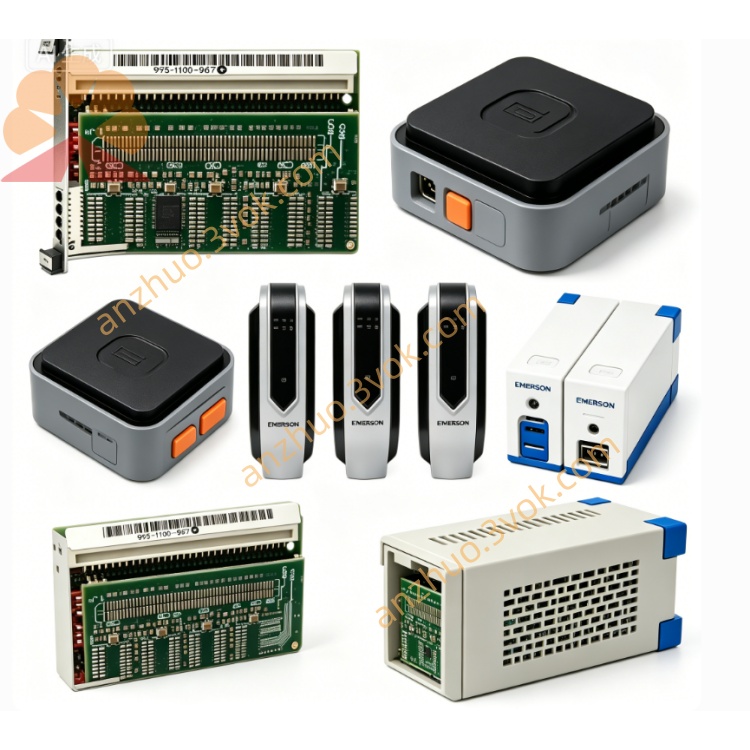
405A689G03
Description
Key Specifications
Model: 405A689G03
Manufacturer: Westinghouse / Emerson
Compatible Systems: WDPF, Ovation DCS
Type: SMS 8007 Disk Controller Board
Revision: Typically Rev 6 (latest production revision)
Function: Hard disk/optical storage control, data buffering, MultiBus interface
Bus Interface: MultiBus (WDPF/Ovation backplane compliant)
Onboard Memory: Improved ECC RAM (vs. G01)
Power: +5 VDC, ±12 VDC (from backplane)
Dimensions: Standard 6U DCS module (≈ 12 × 8 × 1 in / 305 × 203 × 25 mm)
Weight: ≈ 1.1 lb (0.5 kg)
Status: Obsolete (EOL);available as NOS or refurbished
Warranty: 12 months (refurbished);24 months (NOS)
Main Features
Upgraded SMS 8007 firmware/hardware – fixes known bugs in G01, improves stability with modern disk emulators.
Enhanced ECC memory – better error protection for critical control data.
Full backward compatibility – directly replaces 405A689G01 in any WDPF/Ovation slot.
Hot‑swap capable – online replacement without system shutdown (system‑dependent).
Robust industrial design – conformal coating, extended temperature tolerance for 24/7 operation.
Applications
Power Generation: Thermal, nuclear, combined‑cycle plants (legacy WDPF/Ovation DCS).
Process Industries: Petrochemical, pulp & paper, cement, water treatment.
Migration & Maintenance: Ideal upgrade for aging G01 controllers; works with disk emulators (SSD replacements) to extend system life.
405A689G03 vs. G01
| Feature | 405A689G03 | 405A689G01 |
|---|---|---|
| Revision | Rev 6 (latest) | Rev 1–5 |
| Memory | ECC, higher capacity | Non‑ECC, smaller |
| Firmware | Updated, bug‑fixed | Original, known issues |
| Compatibility | 100% drop‑in for G01 | Original version |
| Price (used) | Slightly higher | Lower |
Installation (Manual Excerpt)
Power off the chassis; wait 5 minutes for capacitors to discharge.
Insert 405A689G03 into any available MultiBus slot.
Secure the front‑panel screw to ensure proper grounding.
Connect disk/emulator cables to the board’s I/O connectors.
Power on; verify LEDs: green = power OK, yellow = activity.
Maintenance
Quarterly: Inspect connectors for corrosion; clean with dry, low‑pressure air.
Static Protection: Always use an ESD wristband when handling the board.
Replacement: G03 is the preferred replacement for failed G01 units.
LED Indicators
Green (PWR): ON = normal power.
Yellow (ACT): Blinking = data transfer.
Red (FLT): ON = communication/device error.
Get a Quote