405A689G01
Description
Key Specifications
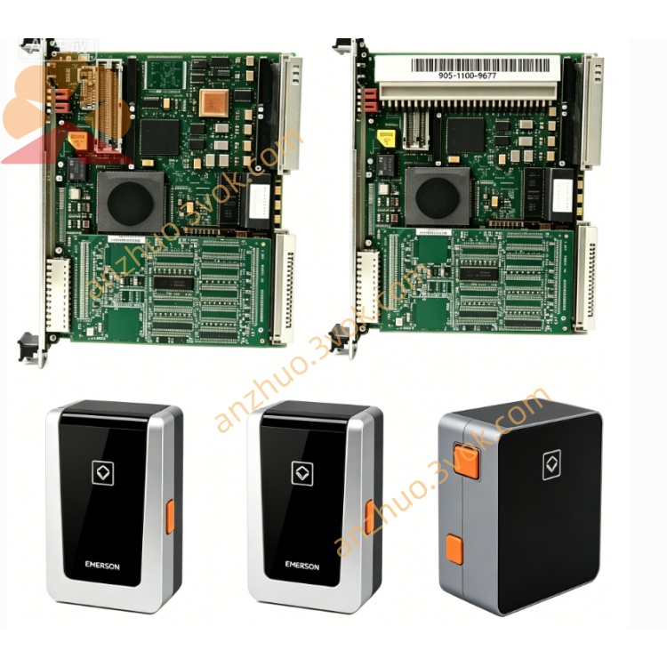
Model: 405A689G01
Manufacturer: Westinghouse / Emerson
Compatible Systems: WDPF, Ovation DCS
Type: SMS 8007 Disk Controller Board
Function: Disk storage control, data communication
Bus Interface: MultiBus (compatible with WDPF/Ovation backplane)
Power Supply: +5 VDC, ±12 VDC (from backplane)
Dimensions (W×H×D): Standard 6U DCS module size
Weight: Approx. 0.8 kg
Status: Obsolete (EOL);available as NOS (New Old Stock) or refurbished
Warranty: 12 months (refurbished);24 months (NOS)
Main Features
Dedicated disk control – manages data read/write operations for DCS storage devices.
High-speed MultiBus communication – ensures fast and reliable data transfer with the main controller.
Industrial-grade reliability – designed for continuous operation in harsh industrial environments.
Full legacy compatibility – works with existing WDPF/Ovation systems for maintenance and migration.
Hot-swap support – can be replaced online without system shutdown (system-dependent).
Applications
Power Generation: Thermal, nuclear, combined-cycle power plants (WDPF/Ovation DCS).
Process Industries: Petrochemical, pulp & paper, cement, water treatment facilities.
DCS Maintenance: Replacement controller board for legacy WDPF/Ovation installations.
Related Models
405A689G01: SMS 8007 Disk Controller Board (base model)
405A689G03: SMS 8007 Disk Controller Board (revised version)
405A675G series: 12-slot MultiBus chassis (for module mounting)
405A685G series: 12-slot MultiBus chassis (revised chassis)
Installation (Manual Excerpt)
Power off the DCS chassis and wait 5 minutes for capacitors to discharge.
Insert the 405A689G01 board into an available MultiBus slot.
Ensure the board is fully seated and secured with front-panel screws.
Connect disk storage cables to the board’s interface connectors.
Power on the chassis and verify the board’s LED indicators.
Maintenance
Quarterly Inspection: Check connectors for dirt/corrosion; verify cable connections.
Cleaning: Use dry, low-pressure compressed air to clean the board surface and connectors.
Safety: Disconnect all power before servicing; avoid static electricity damage.
LED Indicators
Green (Power): ON = normal power supply.
Yellow (Activity): Blinking = data transfer in progress.
Red (Fault): ON = board/disk communication error.
Get a Quote