405A675G63
Description
Key Specifications
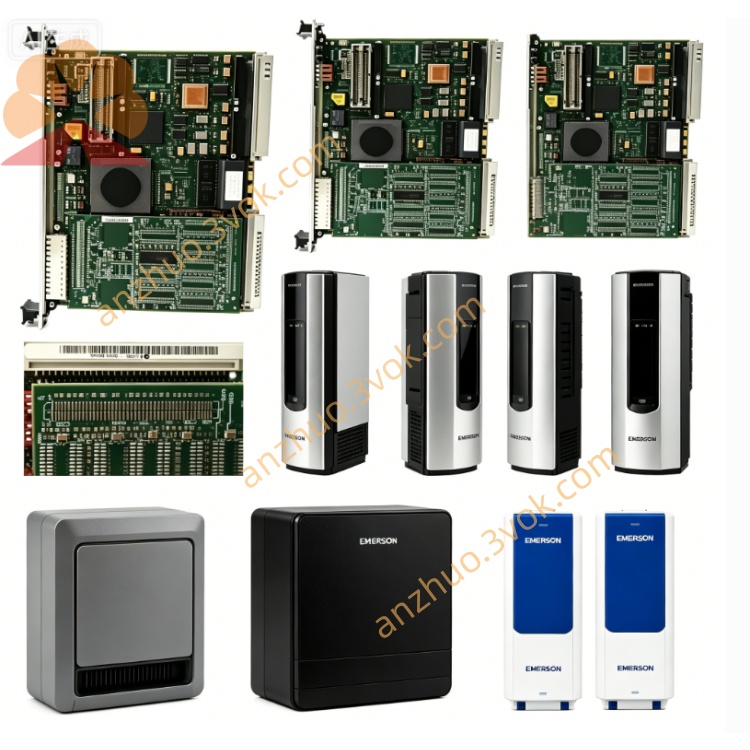
Model: 405A675G63
Manufacturer: Westinghouse / Emerson
System Compatibility: WDPF, Ovation DCS
Type: 12‑slot MultiBus chassis (backplane assembly)
Slots: 12 module positions
Backplane: MultiBus parallel bus, high‑speed inter‑module communication
Input Power: 115 VAC (integrated power supply)
Mounting: Standard 19” industrial rack
Dimensions (W×H×D): approx. 483 × 133 × 280 mm
Weight: approx. 4.5 kg
Status: Obsolete (EOL);available as NOS or refurbished
Warranty: 12 months (refurbished);24 months (NOS)
Main Features
12‑slot high‑density design – flexible system configuration for up to 12 modules.
MultiBus backplane – reliable, high‑speed data exchange between controllers and I/O.
Integrated 115 VAC power – powers backplane and modules, reduces external wiring.
Rugged industrial construction – heavy‑duty metal, card guides, EMI shielding.
Hot‑swap capable – modules can be inserted/removed online (system‑dependent).
Full legacy compatibility – works with WDPF/Ovation hardware for maintenance and migration.
Applications
Power generation (thermal, nuclear, combined‑cycle plants)
Process industries (petrochemical, pulp & paper, cement, water treatment)
DCS maintenance / spare parts replacement for existing WDPF/Ovation systems
Related Models
405A675G21: 4‑slot power supply chassis (24 VDC, 10 A)
405A675G33: 12‑slot MultiBus chassis (similar, different revision)
405A675G61: 12‑slot MultiBus chassis (similar, different revision)
405A675G62: 12‑slot MultiBus chassis (similar, different revision)
Installation (Manual Excerpt)
Mount chassis to standard 19” rack with 4 front‑panel screws.
Connect 115 VAC to chassis power inlet.
Insert modules into slots 1–12; ensure full seating and locking.
Verify module LEDs: green = power OK.
Maintenance
Quarterly: Inspect backplane connectors for dirt/corrosion; check module seating and fasteners.
Cleaning: Use dry, low‑pressure compressed air to clean slots/connectors.
Safety: Disconnect AC before servicing; wait 5 minutes for capacitor discharge.
LED Indicators (on Modules)
Green (Power): ON = normal power
Red (Fault): ON = backplane/module fault (overvoltage, overcurrent, communication error)
Get a Quote