405A675G61
Description
Key Specifications
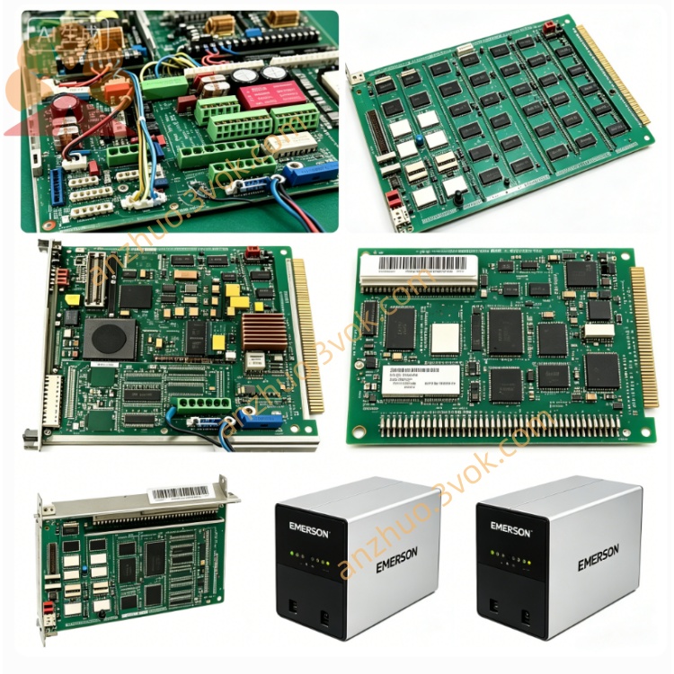
Model: 405A675G61
Manufacturer: Westinghouse / Emerson
Compatible Systems: WDPF, Ovation DCS
Type: 12‑slot MultiBus chassis (backplane assembly)
Slot Count: 12 module positions
Backplane: MultiBus parallel bus, high‑speed inter‑module communication
Input Power: 115 VAC (integrated power supply)
Mounting: Standard 19” industrial rack
Dimensions (W×H×D): ~483 × 133 × 280 mm
Weight: ~4.5 kg
Status: Obsolete (EOL);available as new old stock (NOS) or refurbished
Warranty: 12 months (refurbished);24 months (NOS)
Main Features
12‑slot high‑density design: Accommodates up to 12 DCS modules for flexible system configuration.
MultiBus backplane: Ensures reliable, high‑speed data exchange between controllers and I/O modules.
Integrated AC power: 115 VAC input powers the backplane and installed modules, reducing external wiring.
Rugged industrial construction: Heavy‑duty metal chassis with card guides and EMI shielding for harsh environments.
Hot‑swap capable: Modules can be inserted/removed online (system‑dependent) without shutdown.
Full compatibility: Works with legacy WDPF and Ovation DCS hardware for easy maintenance and migration.
Applications
Power Generation: Thermal, nuclear, combined‑cycle power plants (legacy WDPF/Ovation systems).
Process Industries: Petrochemical, pulp & paper, cement, water treatment facilities.
DCS Maintenance & Spares: Replacement chassis for existing WDPF/Ovation DCS installations.
Related Models
405A675G21: 4‑slot power supply chassis (24 VDC, 10 A).
405A675G33: 12‑slot MultiBus chassis (similar to 405A675G61, different revision).
405A672H01: DIN‑rail mounted 24 VDC power supply.
Installation & Maintenance (Excerpt from Manual)
Installation
Mount the chassis to a standard 19” rack using 4 screws (front panel).
Connect 115 VAC power to the chassis inlet.
Insert modules into slots 1–12, ensuring proper seating and locking.
Verify all module LEDs illuminate as expected (green = power OK).
Maintenance
Quarterly Inspection: Check backplane connectors for dirt/corrosion; verify module seating and screw tightness.
Cleaning: Use dry, low‑pressure compressed air to blow dust from slots and connectors.
Safety: Disconnect AC power before servicing; wait 5 minutes for capacitors to discharge.
LED Indicators (on Modules, not Chassis)
Green (Power): On = module powered normally.
Red (Fault): On = backplane/module fault (overvoltage, overcurrent, communication error).
Get a Quote