405A528G01
Description
Technical Specifications
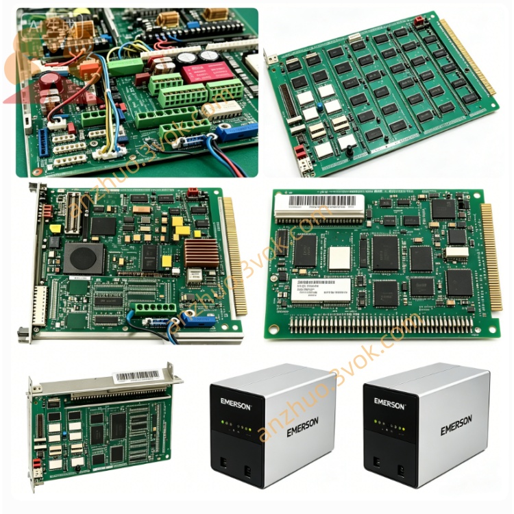
Model: 405A528G01
Manufacturer: Westinghouse (Emerson)
System Compatibility: WDPF DCS, Ovation™ DCS (legacy)
Type: 12‑slot MultiBus chassis (backplane + enclosure)
Backplane: IEEE 796 Multibus (P1 bus), 12 slots
Slots: 12 module positions (supports CPU, I/O, power supply modules)
Input Power: 115/230 VAC, 50/60 Hz (via integrated power supply)
Cooling: Dual integrated cooling fans, front‑to‑back airflow
Mounting: 19” standard rack‑mount (EIA compliant)
Dimensions (H×W×D): ~13.3 × 44.5 × 50.8 cm (5.25” × 17.5” × 20”)
Weight: ~15.9 kg (35 lb) (empty)
Key Features: Hot‑swappable module support, redundant power supply compatibility, EMI shielding, built‑in line filter
Variants:
405A528G01: 12‑slot, 115/230 VAC
405A528G02: 12‑slot, 230 VAC
405A528G61/G62: 12‑slot, 115/230 VAC (high‑temp)
Application Fields
Power Generation: WDPF/Ovation DCS control room chassis for power plant DPU controllers, I/O modules, and redundant power supplies.
Process Industries: Petrochemical, pulp & paper, cement — 19” rack‑mounted DCS chassis for distributed control nodes.
Legacy System Upgrades: Replacement chassis for aging WDPF installations, fully interoperable with original modules.
Installation & Wiring
Rack Mounting: Secure chassis to 19” EIA rack using front panel mounting brackets; ensure adequate rear clearance for airflow.
Power Connection: Connect 115/230 VAC to chassis power inlet; verify voltage setting matches supply.
Module Insertion: Insert DPU, I/O, and power supply modules into slots (follow slot assignment rules: CPU in slot 0, power supplies in dedicated slots).
Backplane Cabling: Connect Multibus P1 connectors between chassis (if multi‑chassis system); ensure proper grounding.
Cooling Check: Verify fans operate; keep front/rear vents unobstructed for airflow.
Operation & Diagnostics
PWR (Green): Chassis input power normal.
FAN (Green): Cooling fans operational.
FAULT (Red): Overheating, fan failure, or backplane voltage fault.
Module Status: Individual module LEDs indicate power, communication, and fault status.
Maintenance & Safety
Maintenance: Clean air filters quarterly; inspect backplane connectors for corrosion; verify fan operation monthly.
Safety: Disconnect AC power before servicing; allow 5 minutes for capacitors to discharge.
Operating Limits: Ambient temperature 0–50 °C; avoid blocking ventilation slots.
Product Status
Current Status: Obsolete (legacy WDPF platform); new old stock (NOS) and refurbished units available.
Compatibility: Fully compatible with all WDPF/Ovation modules (e.g., 405A431G01/G02 power supplies, 1C311xx I/O modules).
Get a Quote